Power supply device

a power supply device and power supply technology, applied in the direction of greenhouse gas reduction, process and machine control, instruments, etc., can solve the problems of limited continuous operation period of the device and damage to the fuel cell, and achieve the effect of restricting the current backflow and preventing the degradation of the fuel cell

Inactive Publication Date: 2008-02-14
PANASONIC CORP
View PDF9 Cites 27 Cited by
  • Summary
  • Abstract
  • Description
  • Claims
  • Application Information

AI Technical Summary

Benefits of technology

[0017]The present invention, which was worked out in consideration of the peculiar problems in power supply devices employing a fuel cell, has an object to provide a power supply device which can prevent degradation of a fuel cell by using a synchronous-rectification switching power source having a power loss smaller than that of a non-synchronous-rectification DC-DC converter using diode to thereby restrict the current back flow to the fuel cell.
[0019]In the configuration, the output power of the fuel cell is supplied to the load connected between the first and second lead terminals by the synchronous-rectification switching power-source portion. In addition, when the output current of the fuel cell detected by the current-detecting portion is not larger than the preset current threshold, the first and second switching elements are turned off simultaneously by the controller, and thus, even when the output current of the fuel cell is lowered, preventing the output current of the energy storage element flows back via the first and second switching elements to the fuel cell, protecting the fuel cell from degradation.

Problems solved by technology

However, when such a device is operated by using a secondary battery, the continuous operational period of the device is limited, because of restriction in battery capacity.
There remained still problems that, when such an energy storage element is installed in the power supply device employing a fuel cell, use of a small-power-loss synchronous-rectification DC-DC converter may cause current back flow from the energy storage element to the fuel cell, and that it may damage the fuel cell because the fuel cell is characteristically degraded by the current back flow.

Method used


Image

  • Power supply device
  • Power supply device
  • Power supply device

Examples


first embodiment

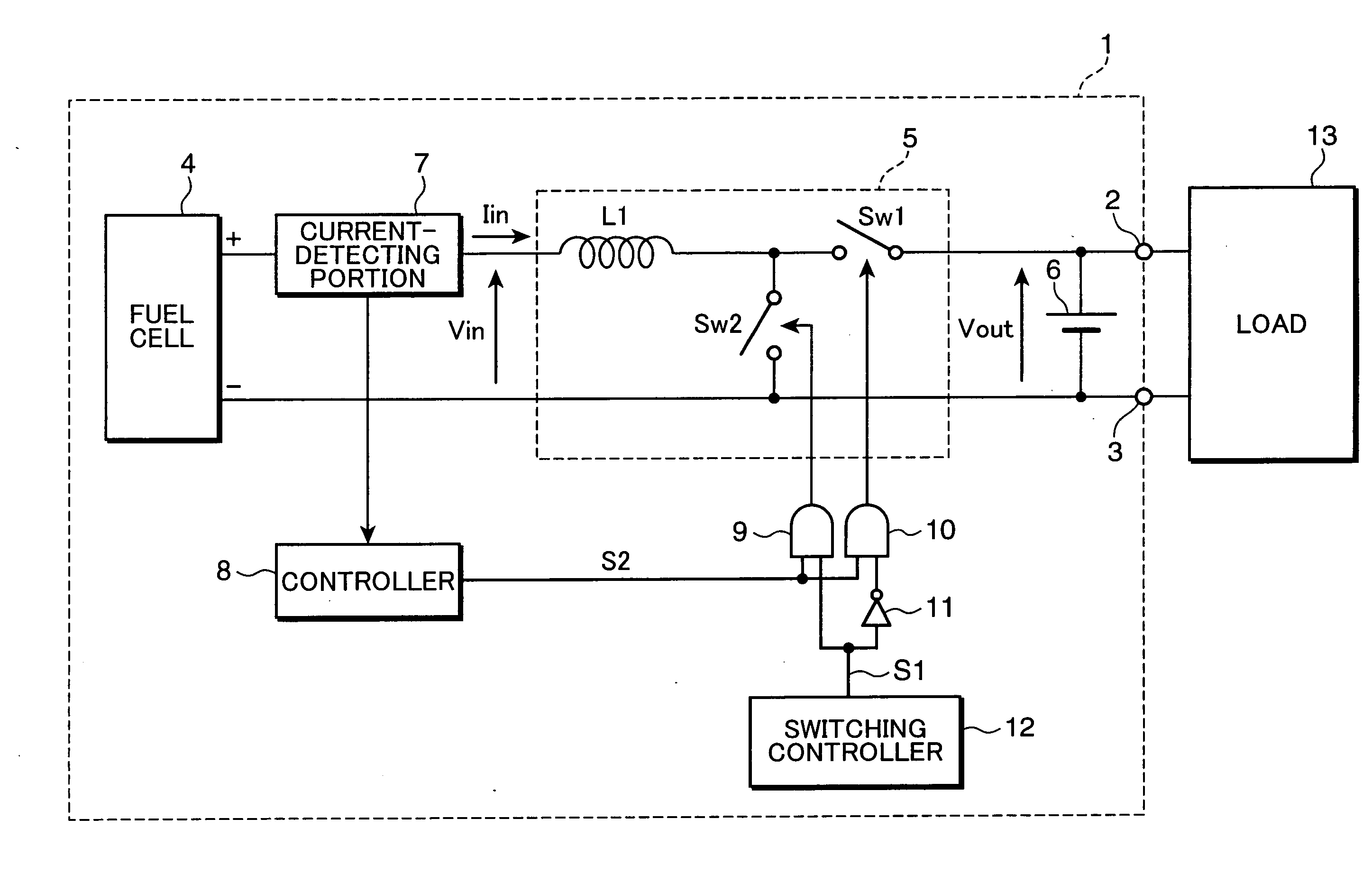
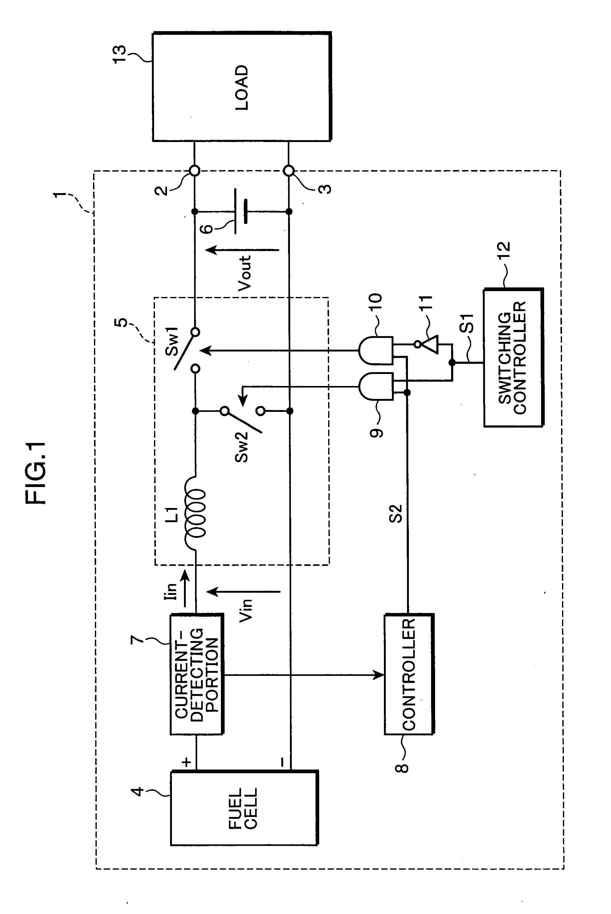
[0029]FIG. 1 is a circuit diagram showing an example of the configuration of the power supply device in the first embodiment of the present invention. The power supply device 1 shown in FIG. 1 has a lead terminal 2 (first lead terminal), a lead terminal 3 (second lead terminal), a fuel cell 4, a DC-DC converter 5, a secondary battery 6 (energy storage element), a current-detecting portion 7, a controller 8, AND gates 9 and 10, an inverter 11, and a switching controller 12 (controller).

[0030]The DC-DC converter 5, the controller 8, the switching controller 12, AND gates 9 and 10, and the inverter 11 form an example of the synchronous-rectification switching power-source portion.

[0031]The DC-DC converter 5 is a so-called synchronous-rectification DC-DC converter that has a coil L1, a switching element SW1 (first switching element), and a switching element SW2 (second switching element). The switching power-source portion is not limited to the case having a DC-DC converter, and thus, m...

second embodiment

[0052]Hereinafter, the power supply device in the second embodiment of the present invention will be described. FIG. 4 is a circuit diagram showing an example of the configuration of the power supply device 1a in the second embodiment of the present invention. The power supply device 1a shown in FIG. 4 is different from the power supply device 1 shown in FIG. 1, in that it has an additional voltage-detecting portion 14 and its controller 8a has a different configuration. The other configuration is the same as that of the power supply device 1 shown in FIG. 1, and description thereof is omitted, and only the configuration characteristic in the present embodiment will be described.

[0053]The voltage-detecting portion 14 detects the output voltage of the fuel cell 4, i.e., the input voltage Vin of the DC-DC converter 5, and outputs the voltage of the input voltage Vin to the controller 8a. The voltage-detecting portion 14 may be, for example, an amplifier bringing the input voltage Vin ...


PUM

PropertyMeasurementUnit
forward voltageaaaaaaaaaa
on-resistanceaaaaaaaaaa
output voltageaaaaaaaaaa

Abstract

A power supply device, comprising first and second lead terminals for connection with a load, a fuel cell, an energy storage element connected between the first and second lead terminals, a synchronous-rectification switching power-source portion for converting the output voltage of the fuel cell to the output voltage of the energy storage element and outputting it to the first and second lead terminals, and a current-detecting portion for detecting the output current of the fuel cell, the switching power-source portion further comprising a first switching element connected to the energy storage element in series, a second switching element connected to the energy storage element in parallel, and a simultaneous-turn-off controller for turning off the first and second switching elements simultaneously when the output current detected by the current-detecting portion is not larger than a preset current threshold.

Description

BACKGROUND OF THE INVENTION[0001]1. Field of the Invention[0002]The present invention relates to a power supply device for converting the power generated in a fuel cell to a particular voltage level and supplying it to a load.[0003]2. Description of the Prior Art[0004]Recently, secondary batteries such as lithium ion battery and nickel metal-hydride battery have been used as the power source for portable electronic devices such as personal computer and electrical machines such as electric tool. However, when such a device is operated by using a secondary battery, the continuous operational period of the device is limited, because of restriction in battery capacity. For example, when portable personal computer is operated with a secondary battery, the continuous power-supply period is usually, for example, about 4 hours.[0005]Recently on the other hand, fuel cells that can supply power continuously for a longer period are attracting attention. In the case of power supply to personal ...

Claims


Application Information

Patent Timeline
Patent Type & Authority Applications(United States)
IPC IPC(8): G05F1/10H01M10/46H02J7/00
CPCH01M8/04559H01M8/04589H01M8/0491H01M8/04955H01M16/006Y02B90/14H02J7/34H02J2001/004Y02B40/90Y02E70/40Y02E60/50H01M2250/10H02J2300/30Y02B40/00Y02B90/10Y02E60/10Y02E60/13
Inventor TAKADA, MASAHIROICHINOSE, TOSHIHIKO
Owner PANASONIC CORP
Why Eureka
Try Eureka