Nanoliter flow rate separation and electrospray device with plug and play high pressure connections and multi-sensor diagnostic monitoring system

a flow rate separation and electrospray technology, applied in the field of fluidics system, can solve the problems of affecting the performance of nanolc, the sensitivity of fluidic system, and the inability to perform nanolc, so as to reduce the complexity of fluidic system, the effect of reducing the complexity and ensuring the effect of sensitivity and efficiency

Active Publication Date: 2008-02-14
CORSOLUTIONS
View PDF14 Cites 70 Cited by
  • Summary
  • Abstract
  • Description
  • Claims
  • Application Information

AI Technical Summary

Benefits of technology

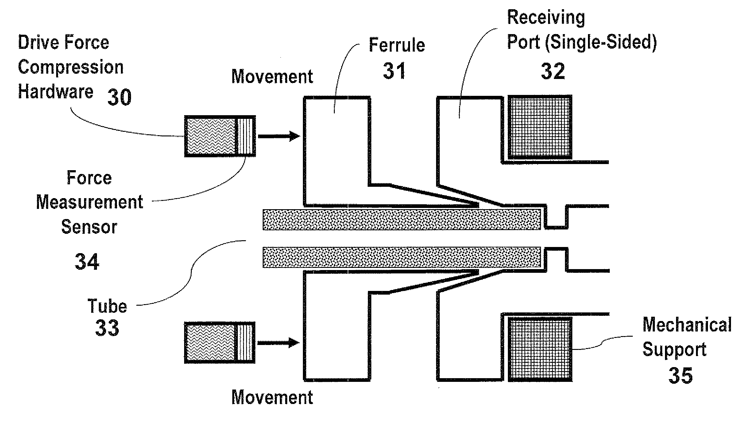
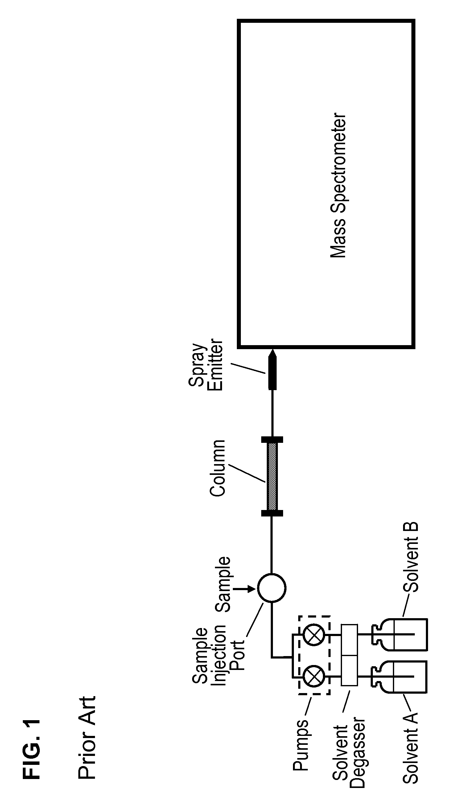
[0018] The present invention reduces the complexity of fluidic systems. Specifically, of nanoLC by allowing a large number of users to successfully perform the technique. The invention encompasses a simple, “pop-into-place” device which has the nanoLC column and spray emitter incorporated within a single structure. Furthermore, all connections are either pre-made or made when the user inserts the device into its holder in front of the mass spectrometer. The connections are automatically sealed with the proper compression

Problems solved by technology

Even with the specialty equipment currently available nanoLC is very difficult to perform.
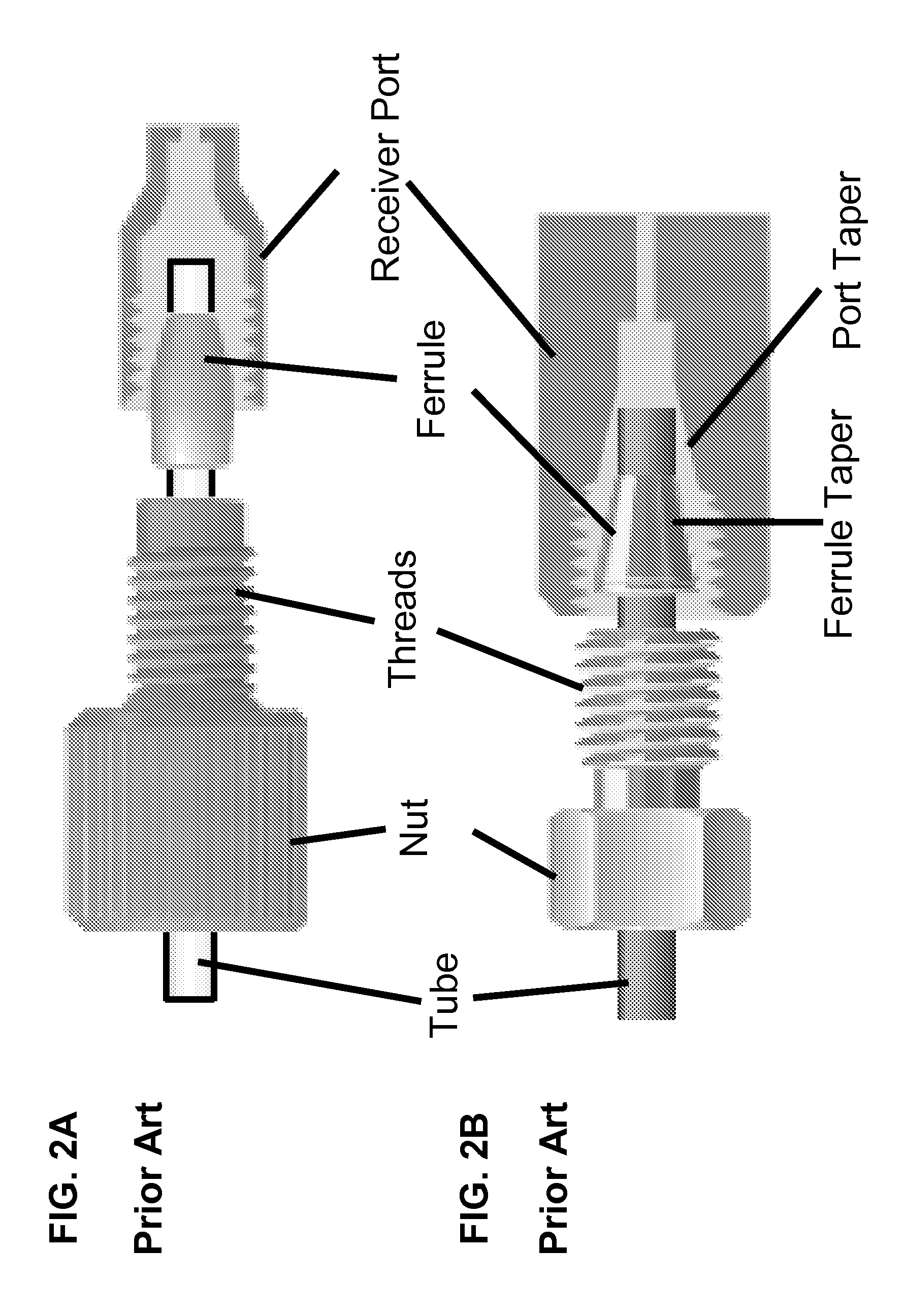
Generally, this leads to over tightening of the fittings which may prevent leaking, however, simultaneously creates a secondary problem.
The over tightening can either damage the tube, the fitting, or the fragile capillaries.
Connecting nanoLC columns is especially difficult as the fragile columns are prone to damage due to frits, stationary phase within the column, or other material in the tube being crushed, cracked, or over compressed.
Additionally, the rotation of the conventional fitting can cause the tube or capillary to be twisted, resulting in grinding or damage from the twisting itself.
Connections between the pumping system and column, and between the column and spray emitter are especially prone to leaks.
Often the leaks are very difficult to detect as evaporation renders the leak unperceivable at the low flow rate or the liquid build up is so small it is difficult to observe.
Leaks at these connections can be due to user error in making connections, or due to a change in the system backpressure which

Method used


Image

  • Nanoliter flow rate separation and electrospray device with plug and play high pressure connections and multi-sensor diagnostic monitoring system
  • Nanoliter flow rate separation and electrospray device with plug and play high pressure connections and multi-sensor diagnostic monitoring system
  • Nanoliter flow rate separation and electrospray device with plug and play high pressure connections and multi-sensor diagnostic monitoring system

Examples


example

[0149] A nanoLC column is constructed and coupled to a nanoelectrospray emitter (the emitter can be the same substrate or a separate substrate and coupled). A “plug and play” fitting is placed on the column's inlet and a second fitting is placed on the column's exit if the column and emitter are to be separate substrates. Conductive sensors with leads are place at the column inlet and between the column's exit and nanoelectrospray emitter connection. All critical alignments are made and the device is casted in a curable or hardening agent (such as a polymer) except for the column inlet and a partial zone at the spray emitter's end. The casting / mold creates an insert in a shape that fits into an accepting device in an accurate and precise orientation. A protective, retractable sheath is incorporated and positioned over the spray emitter end, eliminating the potential for damage by human intervention. The device is now protected and components are fixed in place. The compiled liquid c...


PUM


Abstract

A chromatography and fluidic device with connections capable of automated component changing, diagnostic leak and current sensing. The chromatography-electrospray device contains a chromatography column, a pre-column, a spray emitter, or other fluidic component imbedded within one or more inserts. The inserts are robotically placed in receiving hardware, and a “plug and play” compression fitting connection mechanism makes the fluidic seals in an automated fashion. A plurality of sensors capable of detecting leaks is situated in the device near leak-prone regions. The electrospray emitter has a current sensing electrode in proximity of the electrospray region, capable of detecting the electrospray current. In conjunction with an electronics system, these sensors allow for system and component diagnostics. The diagnostic information may then be used for manual or automated system repair.

Description

CROSS-REFERENCE TO RELATED APPLICATIONS [0001] Reference is made to and priority claimed from U.S. Provisional Application Ser. No. 60 / 822,231, filed Aug. 12, 2006, and its entire contents is hereby incorporated by reference.FIELD OF THE INVENTION [0002] The present invention relates generally to a chromatography and fluidics system, and more specifically to a chromatography electrospray system with “plug and play” connections along with integrated leak and current sensors for monitoring and diagnosing the status of ultra-low level fluidic manipulation. In particular, the present invention relates to an integrated nanofluidic separation system and electrospray device. This achieves a significant advantage over other conventional low-flow chromatography electrospray systems that lack the means and technology to diagnose individual component performance and operation. This present invention allows for component diagnostics in chromatography and fluidic systems. The present invention f...

Claims


Application Information

Patent Timeline
IPC IPC(8): G01N30/02B01L3/00F16L19/00F16L3/00G01N1/10
CPCY10S285/92B01L3/565F16L19/065G01N30/7266B01L2300/0838Y10T137/6851
Inventor VAN PELT, COLLEEN K.
Owner CORSOLUTIONS
Why Eureka
Try Eureka