Control for galvanic corrosion inhibiting coupling

a control system and galvanic corrosion technology, applied in the field of electrochemistry, can solve the problems of inability to monitor the external circuit current in a practical manner, insufficient system of sensing the potential difference between two sensor electrodes as an approximation of the pipe potential difference, and inability to reduce the magnitude of the sensed current, reduce the effect of corrosion

Active Publication Date: 2008-02-28
DNV GL USA INC
View PDF1 Cites 4 Cited by
  • Summary
  • Abstract
  • Description
  • Claims
  • Application Information

AI Technical Summary

Benefits of technology

[0015]In operation, a protection current is applied through the electrolyte between the pair of protection electrodes and the electrical current through the control electrode is sensed. The protection current is adjusted to reduce the magnitude of the sensed current, preferably to zero. In steady state conditions, adjustment of the protection current to bring the sensed current to zero minimizes the galvanic current between the pipes and therefore minimizes corrosion resulting from that galvanic current.

Problems solved by technology

Seawater piping systems on ships and on shore facilities frequently contain dissimilar metal interfaces that pose galvanic corrosion problems.
However, this system of sensing the potential difference between two sensor electrodes as an approximation of the pipe potential difference has been found inadequate.
Consequently, the external circuit current can not be monitored in a practical manner.

Method used


Image

  • Control for galvanic corrosion inhibiting coupling
  • Control for galvanic corrosion inhibiting coupling
  • Control for galvanic corrosion inhibiting coupling

Examples


Embodiment Construction

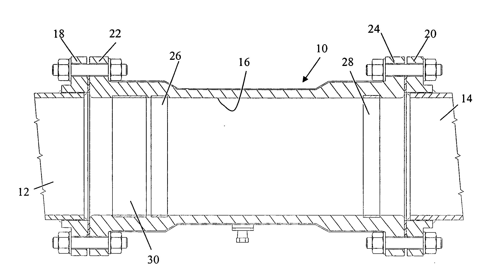
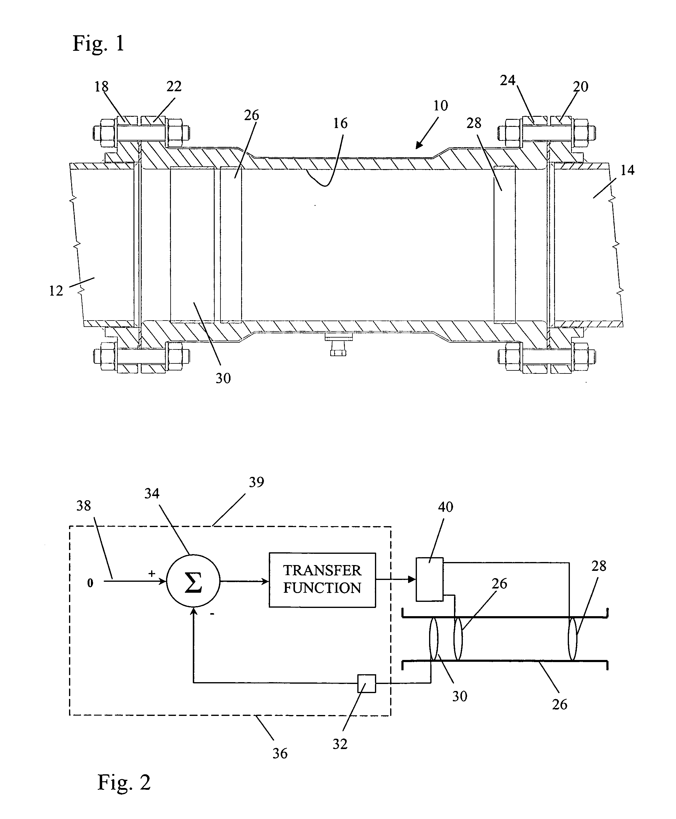
[0024]FIG. 1 illustrates a galvanic corrosion inhibiting coupling 10 joining two electrolyte-conveying pipes 12 and 14. The pipes are constructed of electrochemically dissimilar metals. For example, the pipe 12 may be a nickel based alloy, Inconel 625, and the pipe 14 a Cu-30 Ni alloy. Consequently, the pipe 12 is the relatively more noble metal and the pipe 14 is the relatively more active metal. The coupling 10 is tubular and has an interior wall 16 defining an interior, fluid conveying chamber. The opposite ends of the coupling 10 are adapted for connection to the pipes 12 and 14 so the coupling 10 axially conveys an electrolyte between the pipes. These ends may be conventional in nature such as flanges 18 and 20 that are welded to the pipes 12 and 14 and flanges 22 and 24 formed integrally on the coupling 10 so the respective flanges abut and are bolted together.

[0025]The tubular coupling 10 is preferably constructed of an electrically insulating material, such as a plastic or s...


PUM

PropertyMeasurementUnit
axial lengthaaaaaaaaaa
diameteraaaaaaaaaa
diameteraaaaaaaaaa

Abstract

A pipe coupling for joining two electrolyte-conveying pipes of electrochemically dissimilar metals and inhibiting galvanic corrosion resulting from the dissimilarity. A tubular pipe coupling has a pair of axially spaced protection electrodes mounted to its interior wall in electrical contact with the electrolyte. A control electrode is also mounted to the interior wall of the tubular pipe coupling between one of the pipes and the pair of protection electrodes. A current sensing circuit is connected to sense the galvanic current through the control electrode. A controllably variable source of electrical current is connected to vary the current through the protection electrodes. A negative feedback control circuit receives the sensed current as a feedback signal and controls the variable source to increase the electrical current through the protection electrodes and the electrolyte so that the sensed current is reduced thereby reducing the galvanic current in the electrolyte between the pipes. Preferably, the feedback control system has a reference input representing zero current through the control electrode and therefore drives the protection current to a magnitude that nulls the control electrode current.

Description

(b) CROSS-REFERENCES TO RELATED APPLICATIONS[0001](Not Applicable)(c) STATEMENT REGARDING FEDERALLY-SPONSORED RESEARCH AND DEVELOPMENT[0002](Not Applicable)(d) REFERENCE TO AN APPENDIX[0003](Not Applicable)(e) BACKGROUND OF THE INVENTION[0004]1. Field of the Invention[0005]This invention relates generally to electrochemistry and preventing galvanic corrosion in piping systems that convey fluid electrolytes through adjoining pipes constructed of dissimilar metals and more particularly relates to a control system for a galvanic corrosion inhibiting pipe coupling.[0006]2. Description of the Related Art[0007]Seawater piping systems on ships and on shore facilities frequently contain dissimilar metal interfaces that pose galvanic corrosion problems. The corrosion is the result of the oxidation that occurs at the more active metal when a relatively more noble metal and a relatively more active metal are in electrical contact with an electrolyte and are conductively connected together thro...

Claims


Application Information

Patent Timeline
Patent Type & Authority Applications(United States)
IPC IPC(8): C23F13/00
CPCC23F13/00C23F2213/32C23F2213/31C23F2213/11
Inventor BEAVERS, JOHN A.TOSSEY, BRETT MICHAEL
Owner DNV GL USA INC
Why Eureka
Try Eureka