
Sensor Element for Particle Sensors and Method for Operating the Sensor Element

Inactive Publication Date: 2008-02-28
ROBERT BOSCH GMBH
View PDF8 Cites 37 Cited by
  • Summary
  • Abstract
  • Description
  • Claims
  • Application Information

AI Technical Summary

Benefits of technology

[0005] The sensor element and the method having the characteristic features of the independent claims have the advantage that they allow the object of the exemplary embodiment and / or exemplary method of the present invention to be achieved in an advantageous manner because of the simple design of the sensor element in particular and because of the use of a porous layer in physical contact with a measuring electrode of the sensor element and open for the diffusion of the particles to be determined, which acts both as a particle trap and as an element for smoothing the gas mixture flow reaching the measuring electrode surface. In particular, the sensor element of the exemplary embodiment and / or exemplary method of the present invention is considerably less sensitive to the deposit of larger soot or other particles affecting the electrical conductivity of the sensor element which, in the case of openly accessible measuring electrodes, may possibly result in a short circuit and sudden signal changes of the sensor element. Another advantage results from the fact that particles which have already diffused into the pores of the porous layer may not be re-entrained by turbulence within the gas mixture to be determined. This improves the stability of the measuring signals of the sensor element.
[0007] It is thus advantageous if the measuring electrodes may be intermeshing interdigital electrodes because in this way the electrical resistance, i.e., the electrical conductivity of large surface regions may be determined under defined conditions and thus the sensitivity and quality of the measuring signal may be substantially improved.
[0008] Similar advantages are achieved if the measuring electrodes are situated in different layer levels of the sensor element. This makes it possible to design at least one of the measuring electrodes as a flat electrode, so that a large surface of the sensor element is at least largely covered. The arrangement of the measuring electrodes one on top of the other in different layer levels shortens the conductivity path between the measuring electrodes which must be bridged by soot particles. Thus, in the case of ceramic sensor elements, normally only a resolution of approximately 100 μm of the structures is implementable in the lateral direction, while, in contrast, in the vertical direction, the layer thickness of the structures may be 10 μm to 15 μm. By shortening the distance between the measuring electrodes to be bridged by particles, the time period until the triggering threshold of the sensor element is exceeded is shortened by the same measure, so that the sensor element exhibits a substantially better measuring sensitivity in the case of measuring electrodes arranged on top of each other.

Problems solved by technology

The disadvantage of this type of sensors is, on the one hand, the high cost of their manufacture and, on the other hand, the dependence of the obtained measurement results on the particle size distribution of the soot contained in the measuring gas because both the filter load from coarse particles and the measuring electrode load from fine particles influence the measurement result without the possibility of separating the two influences.

Method used


Image

  • Sensor Element for Particle Sensors and Method for Operating the Sensor Element
  • Sensor Element for Particle Sensors and Method for Operating the Sensor Element
  • Sensor Element for Particle Sensors and Method for Operating the Sensor Element

Examples


Embodiment Construction

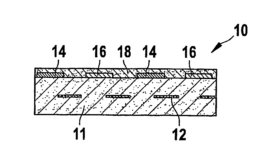
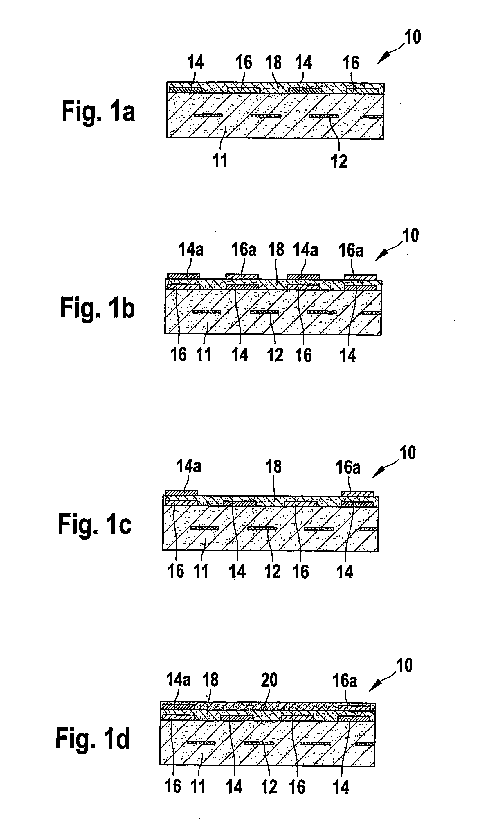
[0019]FIGS. 1a through 1d show a schematic structure of a first specific embodiment of the present invention. Reference numeral 10 denotes a ceramic sensor element for determining a particulate concentration in a gas mixture surrounding the sensor element. Sensor element 10 includes a ceramic substrate 11, an electrically insulating material such as barium-containing aluminum oxide being used as the ceramic material because this material has a largely constant high electrical resistance over a long period of time even when exposed to thermal cycling. Alternatively, the use of cerium dioxide and / or the addition of other alkaline earth oxides is also possible.

[0020] Sensor element 10 also has a ceramic heating element 12 which is designed in the form of a resistive printed conductor and is used for heating sensor element 10, in particular to the temperature of the gas mixture to be determined or for burning off the soot particles deposited on the surface of sensor element 10. The res...


PUM


Abstract

A sensor element for gas sensors for determining the concentration of particulates in gas mixtures, in particular soot sensors having at least one first measuring electrode applied to an electrically insulating substrate and at least one second measuring electrode, a voltage being applicable to the first and second measuring electrodes. The first measuring electrode is at least partly covered by a porous material open to diffusion of the particles to be determined.

Description

FIELD OF THE INVENTION [0001] The present invention is directed to a sensor element and a method for determining the concentration of particulates in gas mixtures, and their use as defined in the preambles of the independent claims. BACKGROUND INFORMATION [0002] As a result of increasingly strict environmental legislation, exhaust gas treatment systems allowing soot particles existing in combustion exhaust gases to be filtered out or eliminated are gaining in importance. In order to check or monitor the operability of such exhaust gas treatment systems, sensors are needed which allow the instantaneous particulate concentration existing in the combustion exhaust gas to be accurately determined even in extended operation. In addition, sensors of this type should allow the load of diesel particulate filters, for example, provided in an exhaust gas system to be predicted in order to achieve a high degree of system reliability, thus allowing the use of more cost-effective filter material...

Claims


Application Information

Patent Timeline
IPC IPC(8): G01N27/26
CPCF01N11/00G01N15/0656G01N27/043G01N1/2252
Inventor SCHMIDT, RALFSIEBERT, MARKUSROESCH, SABINEMARX, HELMUTSCHITTENHELM, HENRIK
Owner ROBERT BOSCH GMBH
Features
  • Generate Ideas
  • Intellectual Property
  • Life Sciences
  • Materials
  • Tech Scout
  • Unparalleled Data Quality
  • Higher Quality Content
  • 60% Fewer Hallucinations
Learn More