
Integrated control and diagnostics systems

a technology applied in the field of integrated control and diagnostics systems, can solve the problems of not being robust enough to operate in real-world applications, many of these systems exhibit nonlinear characteristics, and not finding wide acceptance of “linearizing” techniques, so as to facilitate the maximization of machinery longevity, facilitate the effect of maximizing machinery longevity, and optimum system performan

Inactive Publication Date: 2008-02-28
ROCKWELL AUTOMATION TECH
View PDF34 Cites 37 Cited by
  • Summary
  • Abstract
  • Description
  • Claims
  • Application Information

AI Technical Summary

Benefits of technology

The present invention is a control and diagnostics system for a controlled unit that integrates a diagnostics module with a control module. The system uses advanced machinery diagnostics and non-linear control techniques to optimize the performance of the controlled system and maximize its longevity. The system also predicts when a failure will occur and determines whether to alter the control signal to prevent the failure. The integrated control and diagnostics system provides a cost-effective and intelligent solution for achieving optimal performance and reducing downtime and maintenance costs.

Problems solved by technology

Moreover, many of these systems exhibit nonlinear characteristics.
These “linearizing” techniques have not found wide acceptance because they are generally not robust enough to operate in real-world applications.
Often they are infeasible due to the large number of control inputs required to regulate the system.
Consequently, these techniques have had relatively little use in solving real-world problems.
For instance, the non-linearities associated with the aforementioned servo actuator systems cannot be ignored in control design.
Moreover, such systems may be time varying and may be difficult or impossible to model for control purposes.
Moreover, some diagnostic systems inconveniently require an operator to manually collect data from machinery using portable, hand-held data acquisition probes.
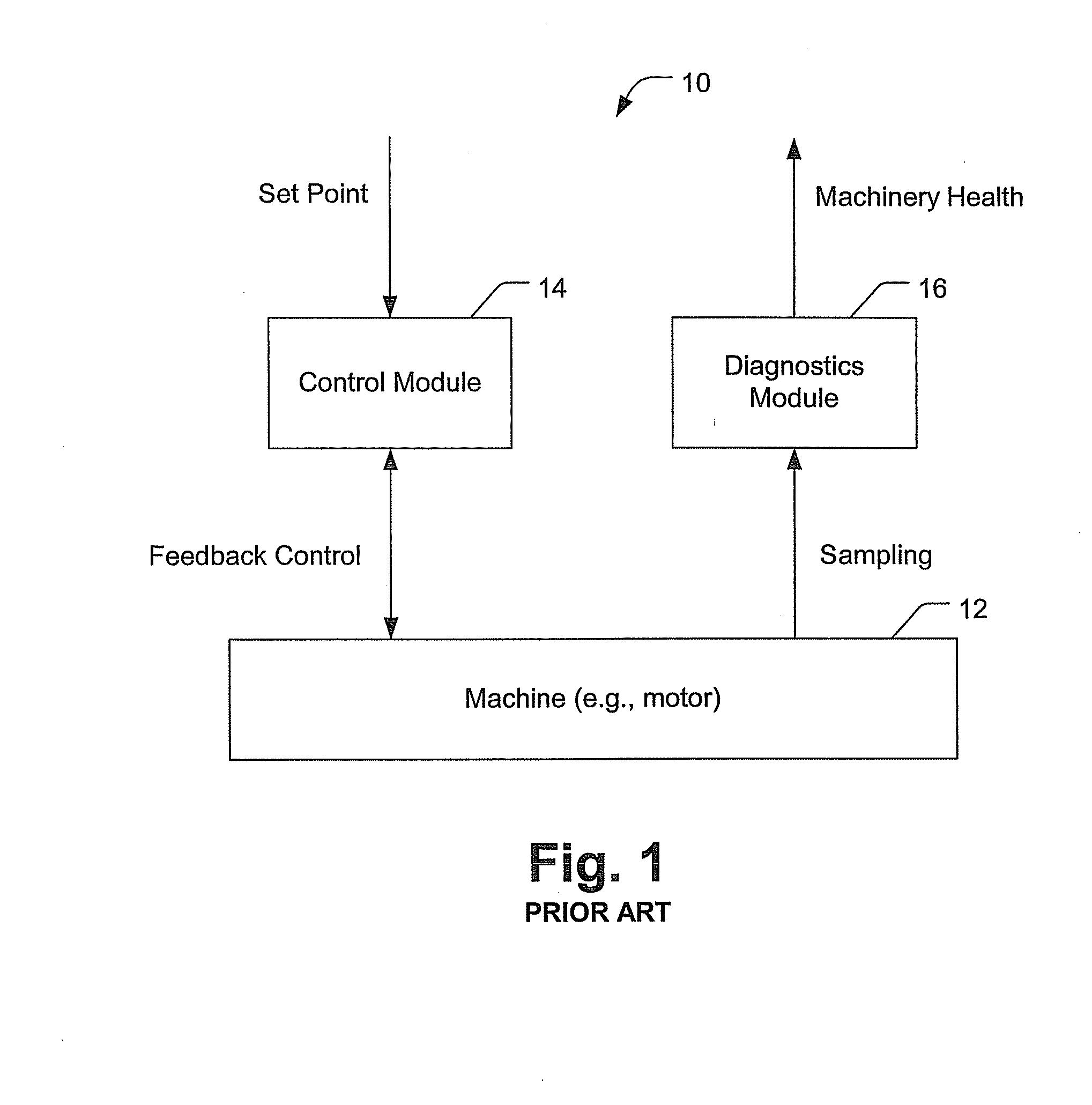
A primary drawback of such a system is that diagnostics block 16 operates independent and isolated from control module 14 and performs off-line diagnostic processing which is not readily adaptable to integration with on-line control.
However, as noted previously, because virtually all diagnostics systems perform off-line diagnostic processing, it has been extremely difficult to implement diagnostics processing real-time in coordination with on-line control.
Presently, no system exists which integrates control and diagnostics to optimize control outputs dynamically in real-time.

Method used


Image

  • Integrated control and diagnostics systems
  • Integrated control and diagnostics systems
  • Integrated control and diagnostics systems

Examples


Embodiment Construction

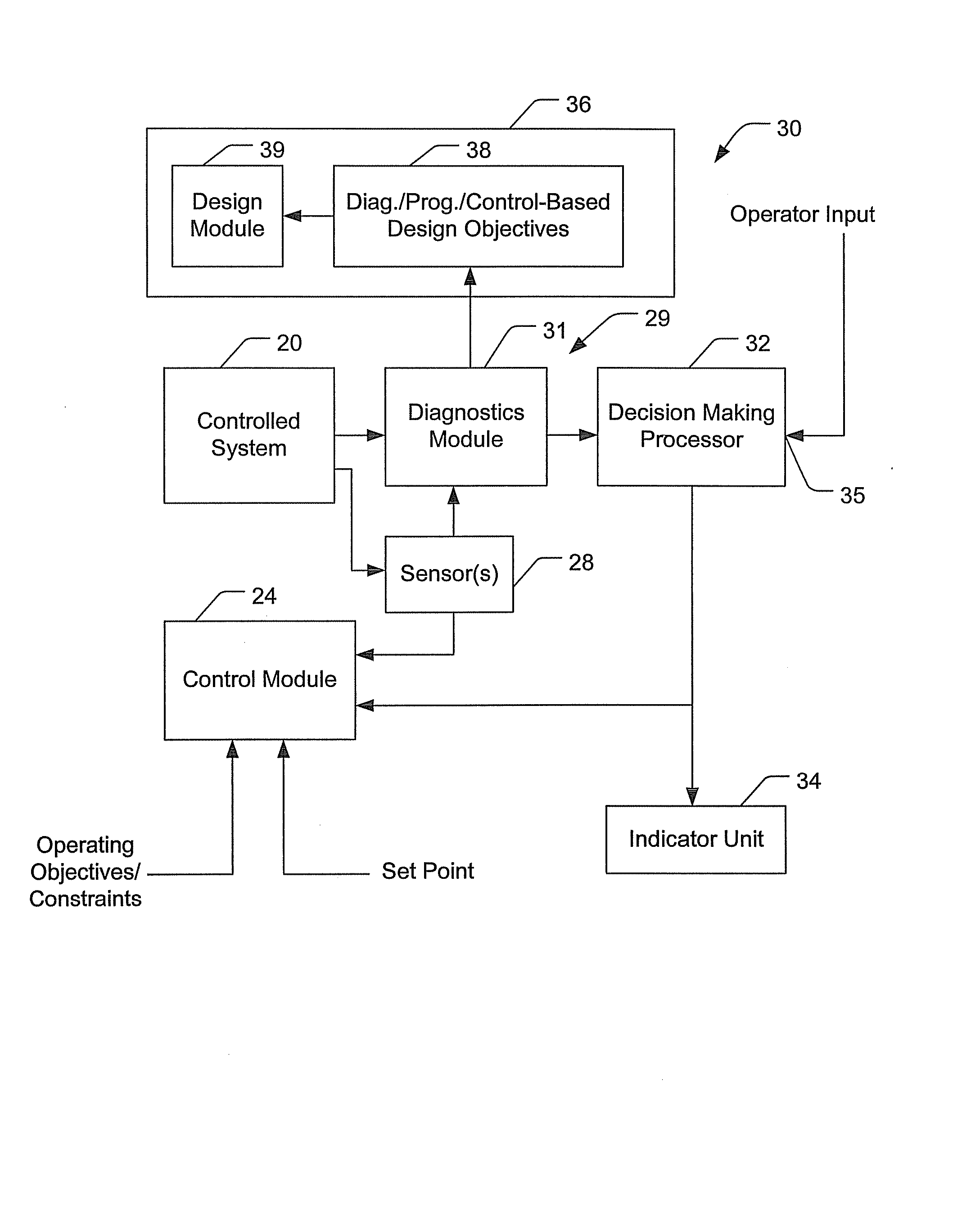
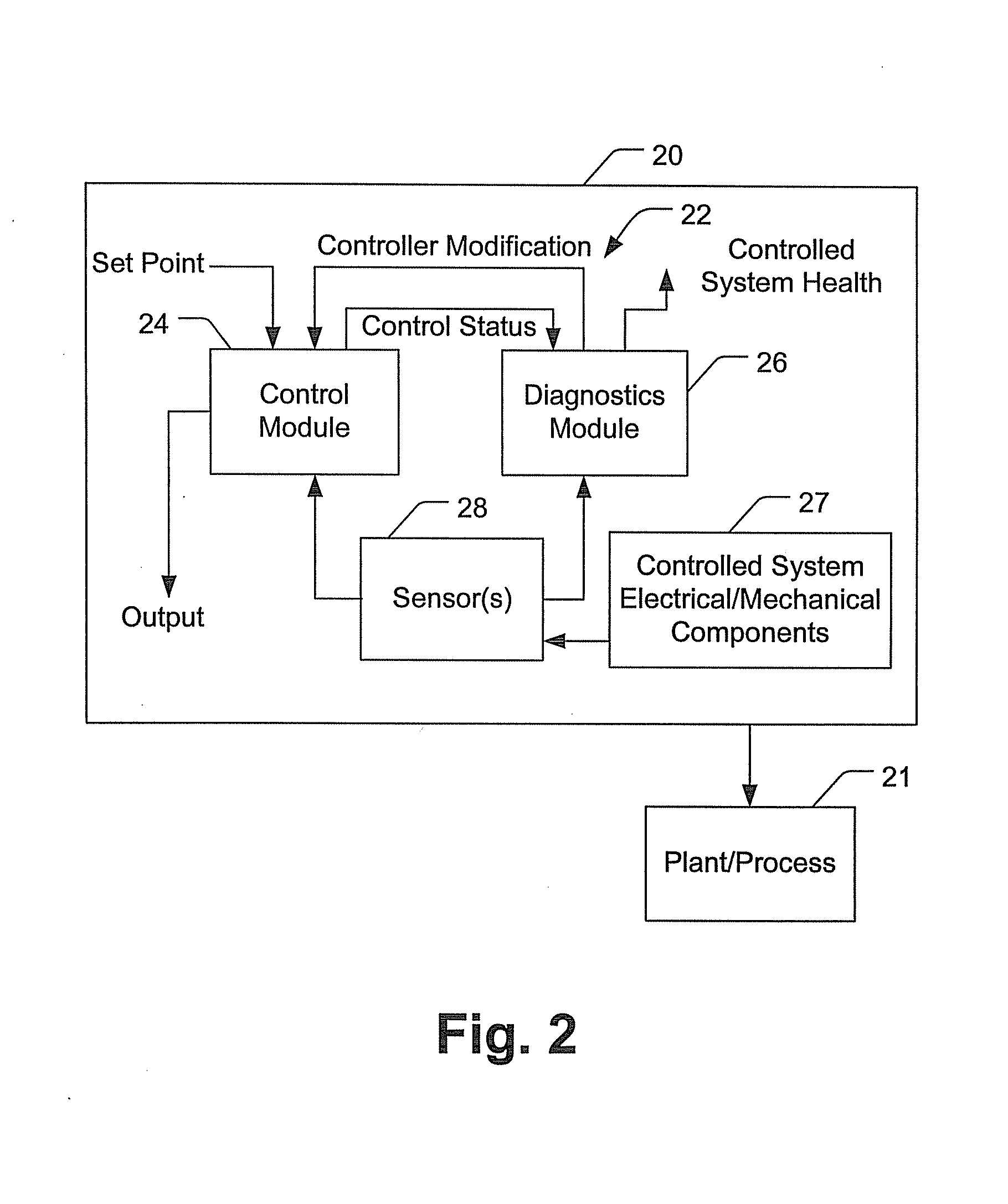
[0027] Turning initially to FIG. 2, a controlled system 20 (e.g., a motor) includes an integrated control and diagnostics system 22 for operating a plant or process 21. System 22 includes both a control module 24 and a diagnostics module 26 in a tightly coupled hybrid configuration. With the integrated configuration, the control and diagnostics modules 24 and 26, respectively, are preferably packaged in a single unit and thus able to share a common set of sensors 28 to collect system data, and a common bus or shared memory to exchange data and information. Sensors 28 preferably comprise a plurality of sensors embedded in controlled system 20 to measure parameters associated with controlled system electrical / mechanical components 27 (for example, stator windings) including, inter alia, motor speed, motor current, voltage, temperature, vibration, magnetic flux, and lubrication characteristics. Although preferably implemented with cost-effective, off-the-shelf sensors, sensors 28 can b...


PUM


Abstract

An integrated control and diagnostics system for a controlled system (e.g., a motor) includes a diagnostics module and a controller coupled to the motor. To optimize operation, the diagnostics information signal is used to modify the control provided by the controller as required. Moreover, the output of the control module is coupled to the diagnostics module so that the health assessment made by the diagnostics module can be based at least in part on the output of the controller. The invention uses a model-based diagnostics approach that allows integration of control algorithms with diagnostics algorithms to intelligently trade off optimizing performance to avert or accommodate failures, and to meet performance requirements in a wide range of applications.

Description

CROSS REFERENCE TO RELATION APPLICATIONS [0001] This application is a continuation Ser. No. 10 / 654,776 filed Sep. 4, 2003, which is a co-pending divisional application U.S. patent application Ser. No. 09 / 911,130, filed on Jul. 23, 2001, which claims the benefit of U.S. patent application Ser. No. 09 / 461,787, now U.S. Pat. No. 6,326,758, filed on Dec. 15, 1999.TECHNICAL FIELD [0002] The present invention is directed generally to systems that perform both control and diagnostics operations on a monitored system, and more specifically, a system in which the diagnostics system is integrated with the control system to provide optimum control and health assessment of the monitored system based on the output of both systems. BACKGROUND OF THE INVENTION [0003] Known control systems typically are feed-forward or feedback systems, which implement closed-loop control to obtain and maintain certain operating conditions. Conventionally, control systems are often used to maintain a prescribed con...

Claims


Application Information

Patent Timeline
Patent Type & Authority Applications(United States)
IPC IPC(8): G05B13/04G05B11/42
CPCG05B19/4063G05B2219/33299H02H7/0844H02P29/022G05B2219/34427H02P29/032
Inventor DISCENZO, FREDERICK M.
Owner ROCKWELL AUTOMATION TECH
Learn More