Ultrasonic diagnostic apparatus and diagnostic method of the apparatus

a diagnostic apparatus and ultrasonic technology, applied in the field of ultrasonic diagnostic apparatus and diagnostic method of the apparatus, can solve problems such as the reduction of diagnostic time, and achieve the effects of reducing the burden on patients and operators, improving throughput, and reducing inspection tim

Inactive Publication Date: 2008-02-28
KK TOSHIBA +1
View PDF6 Cites 30 Cited by
  • Summary
  • Abstract
  • Description
  • Claims
  • Application Information

AI Technical Summary

Benefits of technology

[0009]It is therefore an object of the present invention to provide an ultrasonic diagnostic apparatus and a diagnostic method of this apparatus, wherein scores of stress echocardiography are displayed in accordance with a predetermined report format from 3D volume data, and there is thus no need for the rotation, etc. of an acquired image, leading to an improvement of throughput and reduction in inspection time, such that burdens on a patient and an operator can be reduced.
[0020]According to the present invention, it is possible to provide an ultrasonic diagnostic apparatus and a diagnostic method of this apparatus, wherein scores of stress echocardiography are displayed in accordance with a predetermined report format from 3D volume data, and there is thus no need for the rotation, etc. of an acquired image, leading to an improvement of throughput and reduction in inspection time, such that burdens on a patient and an operator can be reduced.

Problems solved by technology

There is therefore a problem that a short scan time does not result in a reduction of a diagnostic time due to the following format adaptation.

Method used


Image

  • Ultrasonic diagnostic apparatus and diagnostic method of the apparatus
  • Ultrasonic diagnostic apparatus and diagnostic method of the apparatus
  • Ultrasonic diagnostic apparatus and diagnostic method of the apparatus

Examples


first embodiment

[0034]Initially, a first embodiment of the present invention will be described.

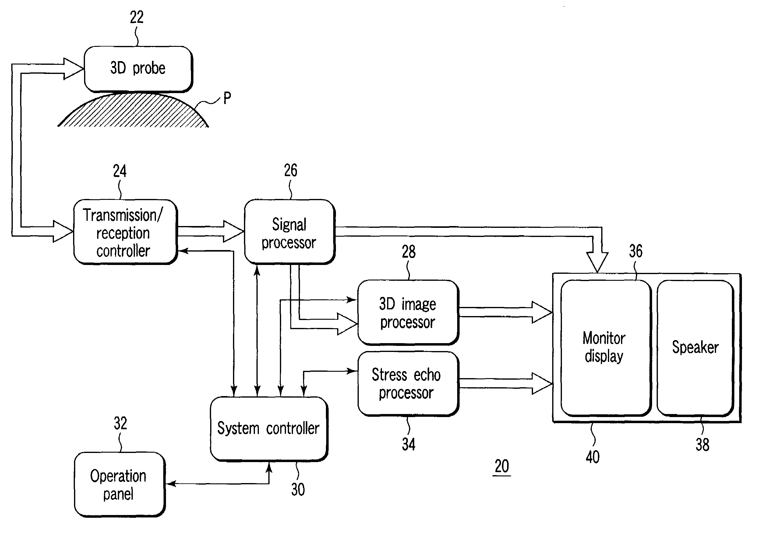
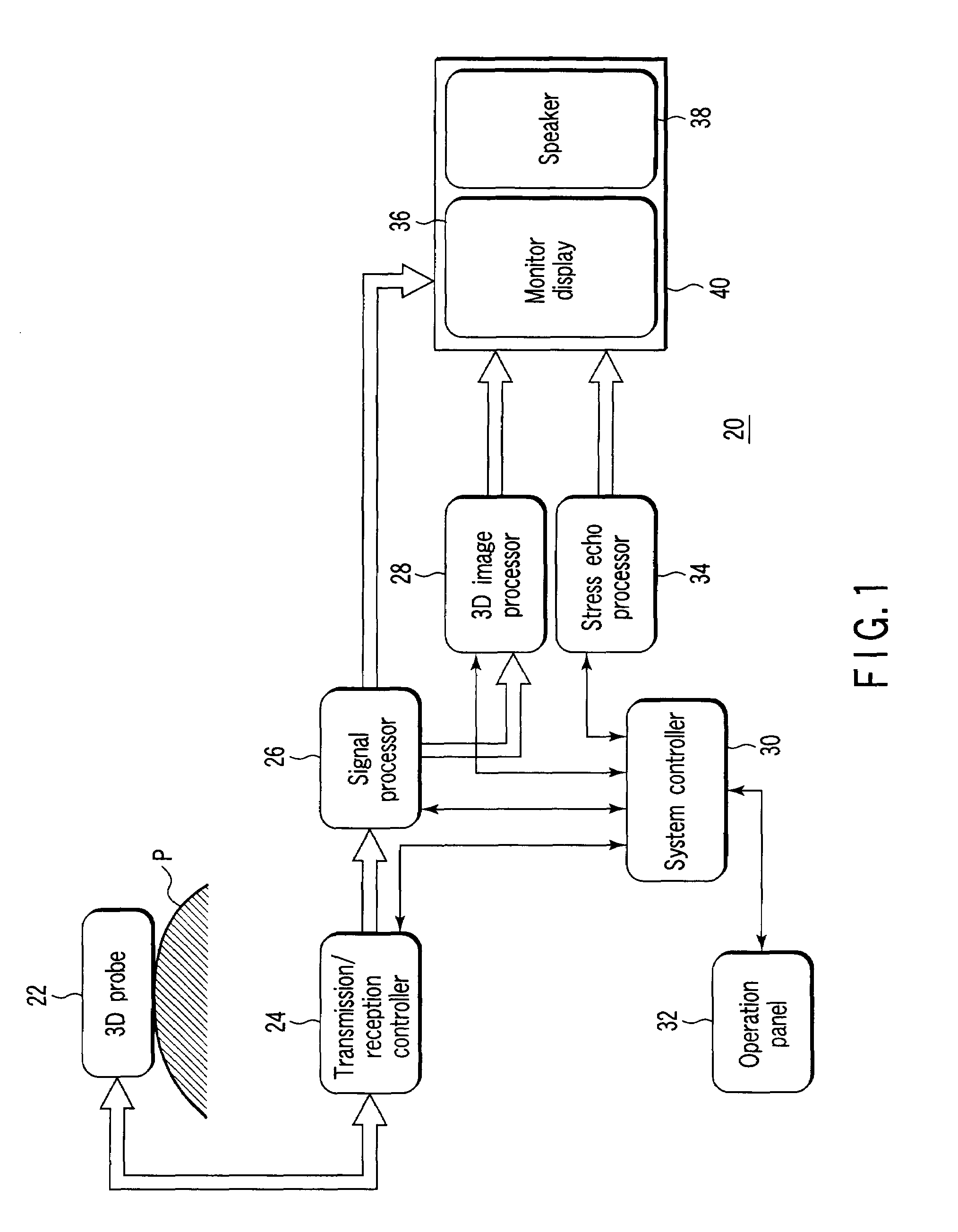
[0035]FIG. 1 is a block diagram showing a schematic configuration of an ultrasonic diagnostic apparatus in a first embodiment of the present invention.

[0036]In FIG. 1, an ultrasonic diagnostic apparatus 20 comprises a three-dimensional ultrasonic probe (3D probe) 22, a transmission / reception controller 24 including a transmission / reception unit, a signal processor 26, a 3D image processor 28, a system controller 30, an operation panel 32, a stress echo processor 34, and an output unit 40 having a monitor display 36 and a speaker 38.

[0037]The 3D probe 22 sends / receives ultrasonic waves to / from a specimen P to obtain an ultrasonic cross-sectional image, and the transmission / reception controller 24 transmits / receives an electric signal to / from the 3D probe 22. The signal processor 26 processes a transmission / reception signal obtained from the transmission / reception controller 24, and generates and stores thr...

second embodiment

[0067]While the positional relation between the 3D probe and the heart is indicated in the first embodiment described above, a warning is issued when a cross-sectional image is not correctly scanned, in a second embodiment.

[0068]In addition, in the present second embodiment, the configuration and basic operation of an ultrasonic diagnostic apparatus are the same as the configuration and operation of the ultrasonic diagnostic apparatus in the first embodiment shown in FIGS. 1 to 10A and 10B. Therefore, the same reference numerals are assigned to the same parts, and different parts alone will be described without diagrammatically showing and describing the same parts.

[0069]FIG. 11 is a diagram showing an example of monitor display layout for the recognition of a positional relation between a 3D probe 22 and a heart 50 in the second embodiment of the present invention. Here, a warning sign (e.g., “warning”) 100 is provided on a screen as to whether a four-chamber cross-sectional image ...


PUM


Abstract

An ultrasonic diagnostic apparatus of the present invention capable of operation with a three-dimensional ultrasonic image performs a scan with a 3D probe for a predetermined time to acquire 3D volume data, and displays a plurality of sections of a heart on a monitor display, in conducting a functional diagnosis of the motion of the heart walls of a specimen before and after the application of a load. Then, the ultrasonic diagnostic apparatus displays a positional relation between the probe and the heart so that display angles of the sections of the heart displayed on the monitor display may be constant.

Description

CROSS-REFERENCE TO RELATED APPLICATIONS[0001]This application is based upon and claims the benefit of priority from prior Japanese Patent Application No. 2006-153574, filed Jun. 1, 2006, the entire contents of which are incorporated herein by reference.BACKGROUND OF THE INVENTION[0002]1. Field of the Invention[0003]The present invention relates to an ultrasonic diagnostic apparatus and a diagnostic method of the apparatus, and more particularly, it relates to an ultrasonic diagnostic apparatus which scans a section of a specimen with an ultrasonic beam and obtains a three-dimensional image and which thus improves the efficiency of three-dimensional image collection / inspection.[0004]2. Description of the Related Art[0005]In an ultrasonic diagnosis, there is a diagnostic method called stress echocardiography which is a functional diagnosis of heart wall motion before and after the application of a load. This method comprises, for example, causing a specimen to jog, taking images of th...

Claims


Application Information

Patent Timeline
Patent Type & Authority Applications(United States)
IPC IPC(8): A61B8/00
CPCA61B5/4884A61B8/08A61B8/0883G01S15/8993A61B8/463A61B8/483G01S7/52074A61B8/14
Inventor ICHIOKA, KENICHIKATAGUCHI, MUNEKI
Owner KK TOSHIBA
Why Eureka
Try Eureka