
Method of fabricating conductive carbon thin-film of high-hardness and application of the carbon thin-film as electrode for thin-film electro-luminescent device

Inactive Publication Date: 2008-03-06
RES & BUSINESS FOUNDATION SUNGKYUNKWAN UNIV
View PDF9 Cites 10 Cited by
  • Summary
  • Abstract
  • Description
  • Claims
  • Application Information

AI Technical Summary

Benefits of technology

[0010]An object of the present invention is to provide a method of growing a carbon thin-film which allows a DLC to have high conductivity while maintaining the superior physical properties thereof.
[0015]The jig is applied a negative DC bias so that carbon ions within plasma can easily arrive at the substrate.
[0020]In another aspect, the present invention provides a method of fabricating a carbon thin-film comprising the steps of: mounting a flexible substrate on a substrate support within a vacuum chamber by forming the flexible substrate on a silicon or glass substrate and washing the flexible substrate with organic solvent; maintaining the initial vacuum of the vacuum chamber at about 10−6 Torr and then supplying argon gas from a gas supply system; maintaining pressure within the vacuum chamber at 10−3 Torr, thereby activating plasma; and applying negative DC bias to the substrate support from a DC bias power supply so that carbon ions existing in the plasma can easily arrive at the flexible substrate, thereby forming a conductive carbon thin-film having a predetermined resistivity.

Problems solved by technology

However, such electrodes have problems in that the fabricating processes are complicated, the manufacturing costs are high, and the metal electrodes are apt to be worn and have corrosive property, which causes oxidation of the thin-film and produces moisture.
The suggested way, however, has disadvantages in that the manufacturing process is complicated and the manufacturing costs increase.
Furthermore, because deposition of such a DLC thin-film according to a conventional method is performed at high temperatures, the structure of the thin-film can be deteriorated, which makes it difficult or impossible to meet the required physical properties of the film.
However, no conventional techniques meet such requirements.

Method used


Image

  • Method of fabricating conductive carbon thin-film of high-hardness and application of the carbon thin-film as electrode for thin-film electro-luminescent device
  • Method of fabricating conductive carbon thin-film of high-hardness and application of the carbon thin-film as electrode for thin-film electro-luminescent device
  • Method of fabricating conductive carbon thin-film of high-hardness and application of the carbon thin-film as electrode for thin-film electro-luminescent device

Examples


Embodiment Construction

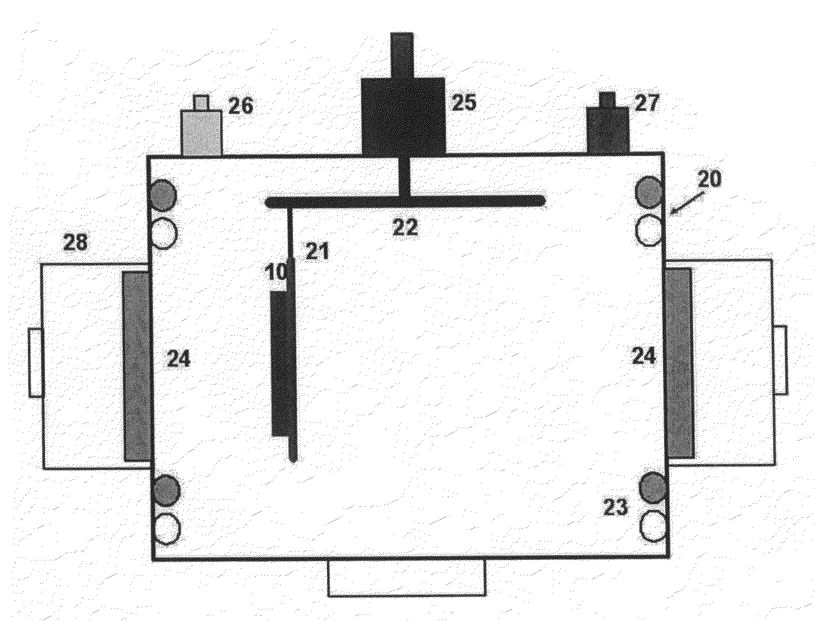
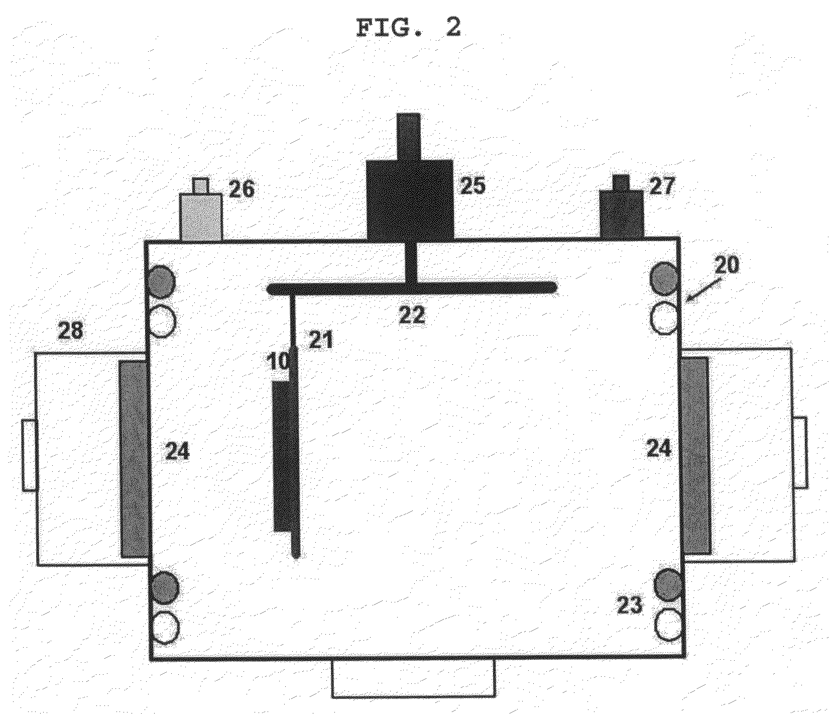
[0034]According to the present invention, a carbon thin-film is grown through closed-field unbalanced magnetron sputtering process. Since closed-field unbalanced magnetron sputtering process can be performed entirely at a low temperature, it is possible to solve a problem related to the temperature of a flexible substrate of an electronic device, which requires deposition performed at room temperature, and the deposition can be uniformly executed on a large area in consideration of commercialization of the carbon thin-film. In particular, if a closed-field unbalanced magnetron sputtering apparatus is employed for high-speed deposition, it is possible to deposit a thicker film within a shorter time, and to exclude the influence of temperature caused by plasma. One technical feature of the present invention is that a conductive thin-film can be fabricated without doping a third material.

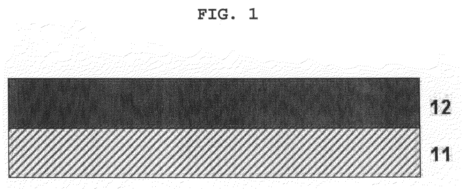
[0035]The present invention fabricates a conductive carbon thin-film of high-hardness on a silicon ...


PUM

PropertyMeasurementUnit
Thicknessaaaaaaaaaa
Thicknessaaaaaaaaaa
Pressureaaaaaaaaaa

Abstract

The present invention provides a method of fabricating a carbon thin-film having high conductivity and high hardness, comprising the steps of: supplying argon (Ar) to the chamber as sputtering gas; maintaining the initial vacuum of the chamber at about 10−6 Torr; forming deposition pressure of about 10−3 Torr so as to activate plasma; and applying negative DC bias to the substrate, and a method of fabricating a thin-film electroluminescent device comprising the steps of: providing a transparent TCO or ITO substrate; forming a phosphor layer on the top of the transparent substrate; forming an insulation layer on the top of the phosphor layer through vacuum deposition; and forming a carbon thin-film electrode through closed-field unbalanced magnetron sputtering.

Description

CROSS-REFERENCE TO RELATED APPLICATION[0001]The present application claims, under 35 U.S.C. §119(a), the benefit of the filing date of Korean Patent Application No. 10-2006-0085225 filed on Sep. 05, 2006, the entire contents of which are hereby incorporated by reference.BACKGROUND OF THE INVENTION[0002]1. Field of the invention[0003]The present invention relates to a method of fabricating a carbon thin-film. More particularly, it relates to a method for growing a carbon thin-film having high conductivity and superior physical properties.[0004]2. Background Art[0005]With the development of the information society, the importance of the exchange of information has increased. In this regard, display devices for displaying image information which are aesthetically pleasing to people occupy an importance position. Recently, with the tendency of demanding flat display devices which are easy to miniaturize and carry, LCDs (Liquid Crystal Displays), PDPs (Plasma Display Panels), FEDs (Field...

Claims


Application Information

Patent Timeline
IPC IPC(8): C23C14/00
CPCC23C14/0605C23C14/345H01L51/5203H01L51/102C23C14/352H10K10/82H10K50/805
Inventor HONG, BYUNGYOUPARK, YONGSEOBCHO, HYUNGJUN
Owner RES & BUSINESS FOUNDATION SUNGKYUNKWAN UNIV
Learn More