Functional Porous Multilayer Fibre and its Preparation

a multi-layer fibre, porous technology, applied in the field of hollow or solid fibres, can solve the problems of limited degree of loading of particulate materials, limited polymeric materials and on the type of particulate materials that can be used, and dense exterior surfaces, etc., to achieve enhanced mechanical stability, maximum functionality, and improved mechanical stability

Inactive Publication Date: 2008-03-06
MOSAIC SYST
View PDF5 Cites 39 Cited by
  • Summary
  • Abstract
  • Description
  • Claims
  • Application Information

AI Technical Summary

Benefits of technology

[0009] It is found that coextrusion of a second porous layer of polymeric material can yield functionalized fibres with a much larger particle content than those disclosed in the art, without being trouble by mechanical instabilities. The benefit of the additional porous layer over the application of a thread or yarn is that the geometry of the fibre is not limited to one in which the functionalized particles are on the outside. Due to the presence of the stability-providing second layer a higher particulate content can be reached, and moreover, a fibre according to the invention with a certain overall particle density, calculated on the basis of the total weight of the fibre, has an improved mechanical stability over one-layer fibres having the same particle density.
[0010] According to the invention the second layer can be either the inner or the outer layer. In the case of the second layer being the shell layer, due to the permeability of the second layer for fluids and gases, the core containing the particles is still accessible and the particles maintain their functionality. In fact, the type of polymer and the porosity of the second layer can then advantageously be fine-tuned such that it is possible to use the outer layer as a sieve for species that are unwanted in the core structure and / or to match the compatibility of the fibre to the conditions of the application. Furthermore, the enhanced mechanical stability brought about by the second layer as the shell layer can yield a fibre having maximum functionality inside.

Problems solved by technology

Disadvantages related herewith are that these processes involve additional process steps after the formation of the fibre to come to a final product and that, depending on the actual process steps that need to be taken to come to the final product, suitable staring materials have to be selected with properties that can sustain the conditions of the additional process steps.
Obviously such a requirement puts limitations on the polymeric material and on the type of particulate material that can be used.
The degree of loading of particulate material will be limited by the force required to reach sufficient stretching of the matrix material to achieve the desired porosity.
% solvent results in rather dense exterior surfaces and limited particle accessibility.
However, an increase in the amount of solvent results in difficulties of controlling the spinning process; due to delayed demixing of the nascent fibre solidification takes too long.
However, the fibre disclosed therein only has a limited degree of loading of particulate material.

Method used


Image

  • Functional Porous Multilayer Fibre and its Preparation
  • Functional Porous Multilayer Fibre and its Preparation
  • Functional Porous Multilayer Fibre and its Preparation

Examples


example 1

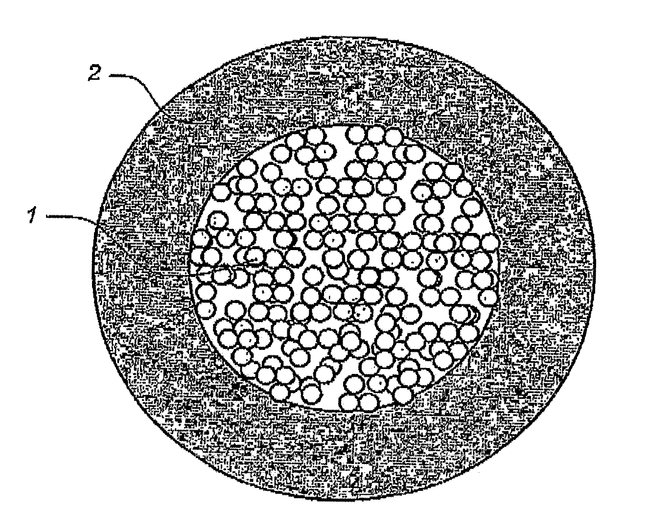
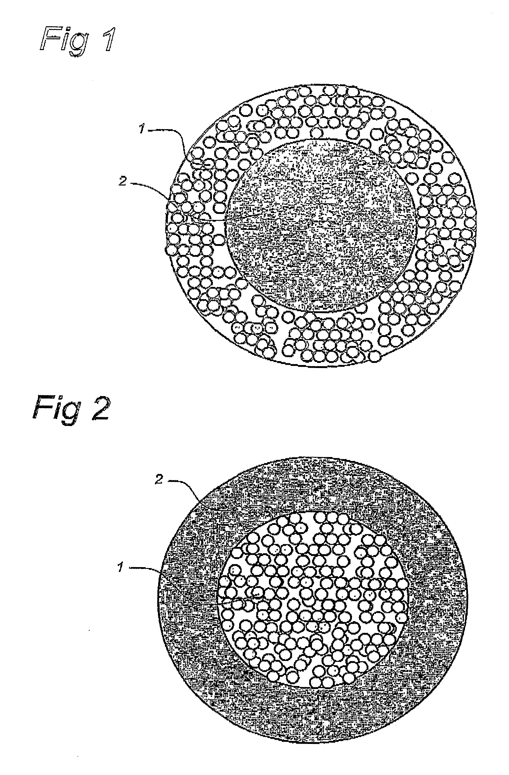
[0060] A homogeneous polymer solution 1 with the following composition was prepared by ring 9.5 wt % polyethersulfon (Ultrason E 6020 P), 24 wt % polyethylene glycol 400, 4.5 wt % PVP, 6.8 wt % dry Sepharose FF (34 μm), 6 wt % water and 49.2 wt % N-Methyl Pyrrolidone (NMP). In addition, a homogeneous polymer solution 2 with following composition was prepared by mixing 16 wt % polyethersulfon (Ultrason E 6020 P), 38.75 wt % polyethylene glycol 400, 38.75 wt % N-Methyl Pyrrolidone and 6.5 wt % water.

[0061] Both solutions were extruded simultaneously through a tube-in-orifice spinneret with the following dimensions: ID tube=0.4 mm, OD tube=0.6 mm, ID mm orifice=1.2 mm. Solution 1 was extruded at a flow rate of 5.1 ml / min through the tube of the spinneret and solution 2 was extruded at a flow rate of 0.51 ml / min through the orifice of the spinneret. After passing an air gap of 45 mm the double layer nascent fibre entered a water bath where phase separation took place. All solutions wer...

example 2

[0065] The same solutions as defined in example 1 were extruded simultaneously through a tube-in-orifice spinneret with the following dimensions: ID tube=0.4 mm, OD tube=0.6, ID mm orifice=1.2 mm. Solution 2 was extruded with a flow rate of 5.1 ml / min through the tube of the spinneret and solution 1 was extruded at a flow rate of 0.51 ml / min through the orifice of the spinneret. After passing an air gap of 45 mm the double layer nascent fibre entered a water bath where phase separation took place.

[0066] This resulted in a double layer fibre with the core layer being layer 2 (no Sepharose particles) and the outer layer being layer 1 (with 40 wt % Sepharose particles based on the total weight of layer 1).

example 3

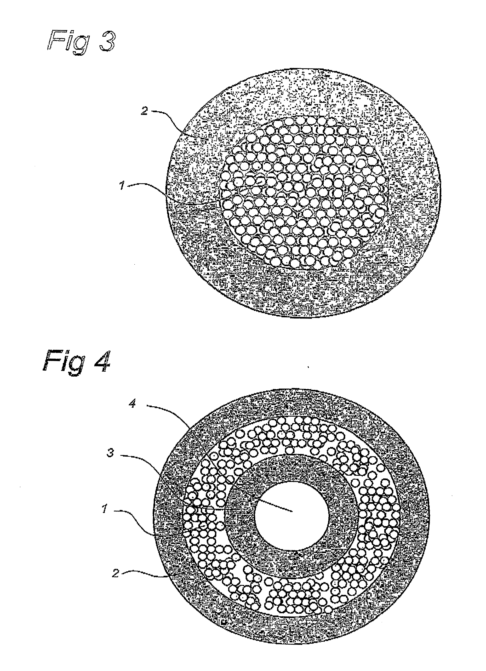
[0067] A homogeneous polymer solution 3 with the following composition was prepared: 15 wt % Bionate® 80A (polycarbonate based polyurethane from The Polymer Technology Group Inc.), 2 wt % PVP K90 and 83 wt % N-Methyl Pyrrolidone (NMP).

[0068] Solution 1 from example 1 and solution 3 were extruded simultaneously through a tube-in-orifice spinneret with the following dimensions: ID tube=0.4 mm, OD tube=0.6 mm, ID mm orifice=1.2 mm, Solution 1 was extruded with a flow rate of 5.1 ml / min through the tube of the spinneret and solution 3 was extruded at a flow rate of 0.51 ml / mm through the orifice of the spinneret. After passing an air gap of 45 mm the double layer nascent fibre entered a water bath where phase separation took place. All solutions were at room temperature.

[0069] This resulted in a double layer fibre similar to the one presented in FIG. 5 (prepared according to example 1) with a highly porous core layer (layer 1) containing Sepharose particles entrapped and a layer 2 at ...


PUM

PropertyMeasurementUnit
wt %aaaaaaaaaa
wt %aaaaaaaaaa
wt %aaaaaaaaaa

Abstract

The invention relates to a hollow or solid fibre having multiple porous layers concentrically arranged, and wherein at least one of the layers comprises functionalized or active particles that are well accessible and maintain their function after preparation. The layer containing high loads of particles can be either the outer or the inner layer. The main function of the other porous layer is to provide mechanical stability to the fibre. It can further act as a sieve and prevent unwanted compounds or species to come in contact with the functionalized particulate matter. Where it is the inner layer, the second layer can advantageously be a biocompatible material. With the second being the outer layer it is now possible to reach a particle content of 100 wt % in the inner layer. These fibres comprising high densities of functionalized particulate matter and of still sufficient mechanical strength can be used for (selective) adsorption, conversion, isolation or purification of compounds from a mixture of compounds, in particular from a fermentation broth, tissue broth, plant broth, cell broth or blood.

Description

TECHNICAL FIELD OF THE INVENTION [0001] The invention relates to a hollow or solid fibre having multiple porous layers concentrically arranged, and wherein one of the layer comprises functionalized or active particles that are well accessible and maintain their function after preparation. The invention also relates to the preparation of such a fibre and to the use of the fibre for (selective) adsorption, conversion, isolation or purification of compounds from a mixture of compounds, in particular from a fermentation broth, tissue broth, plant broth, cell broth or blood. BACKGROUND OF THE INVENTION [0002] In the art methods are known to prepare porous fibres involving the use of particulate material, mostly requiring an additional process step to introduce the desired porosity to the fibre. After the step of preparing the fibre comprising particulate material either particulate material is removed from the non-porous fibre or the non-porous fibre is stretched resulting in porous fibr...

Claims


Application Information

Patent Timeline
Patent Type & Authority Applications(United States)
IPC IPC(8): B01D24/10D01D5/06D01D5/24D01D5/247D01D5/34D01F1/10
CPCD01D5/06D01D5/24Y10T428/2967D01D5/34D01D5/247B01J20/28023B01J20/3293
Inventor KOOPS, GEERT-HENDRIKWESSLING, MATTHIASVAN WIJK, WILLEM DEDERIK
Owner MOSAIC SYST
Why Eureka
Try Eureka