Supercharge Your Innovation With Domain-Expert AI Agents!

Rotary electric machine and stator for rotary electric machines

a technology of rotary electric machines and stators, which is applied in the direction of manufacturing tools, soldering apparatus, and magnetic circuit shapes/forms/construction, etc., can solve the problems of defective insulation in one of the multiphase windings, high temperature of the joint portion of the conductor segment and its surroundings, and the deterioration of the insulating film at the joint portion of the multiphase winding, so as to improve the electrical isolation and the environment resistance of the stator

Active Publication Date: 2008-03-06
DENSO CORP
View PDF33 Cites 9 Cited by
  • Summary
  • Abstract
  • Description
  • Claims
  • Application Information

AI Technical Summary

Benefits of technology

[0012]In order to improve electrical isolation, each of the insulating-film coated joint portions of each of the multiphase windings can be further coated with a resin material. In this case, however, when an insulating film coated at a joint portion of a multiphase winding may be peeled off or cracked by thermal stress applied while the joint portion is formed by welding, the resin material may be difficult to be adhered onto the joint portion. This may deteriorate the environment resistance of the stator.
[0013]Accordingly, an object of at least one aspect of the present invention is to provide rotary electric machines and stators therefor. These rotary electric machines and stators therefor are capable of preventing foreign particles, such as dust particles, electrolyte components, and the like, from staying at a portion of a winding thereof; this portion is close to a joint portion of at least two conductor segments constituting the winding.

Problems solved by technology

This may cause the joint portions of the conductor segments and their surroundings to become high in temperature.
This may cause peeling off or cracking of the deteriorated insulating film, resulting that the foreign particles, such as dust particles, electrolyte components, and the like, may enter the gaps formed due to the peeling-off or cracking and stay there.
This may cause defective insulation in the one of the multiphase windings.
In this case, however, an insulating film coated at a joint portion of a multiphase winding may deteriorate by thermal stress applied while the joint portion is formed by welding.
This may cause peeling off or cracking of the deteriorated insulating film, resulting that the foreign particles, such as dust particles, electrolyte components, and the like, may enter the gaps formed due to the peeling-off or cracking and stay there.

Method used


Image

  • Rotary electric machine and stator for rotary electric machines
  • Rotary electric machine and stator for rotary electric machines
  • Rotary electric machine and stator for rotary electric machines

Examples


Embodiment Construction

[0033]An embodiment of the present invention will be described hereinafter with reference to the accompanying drawings.

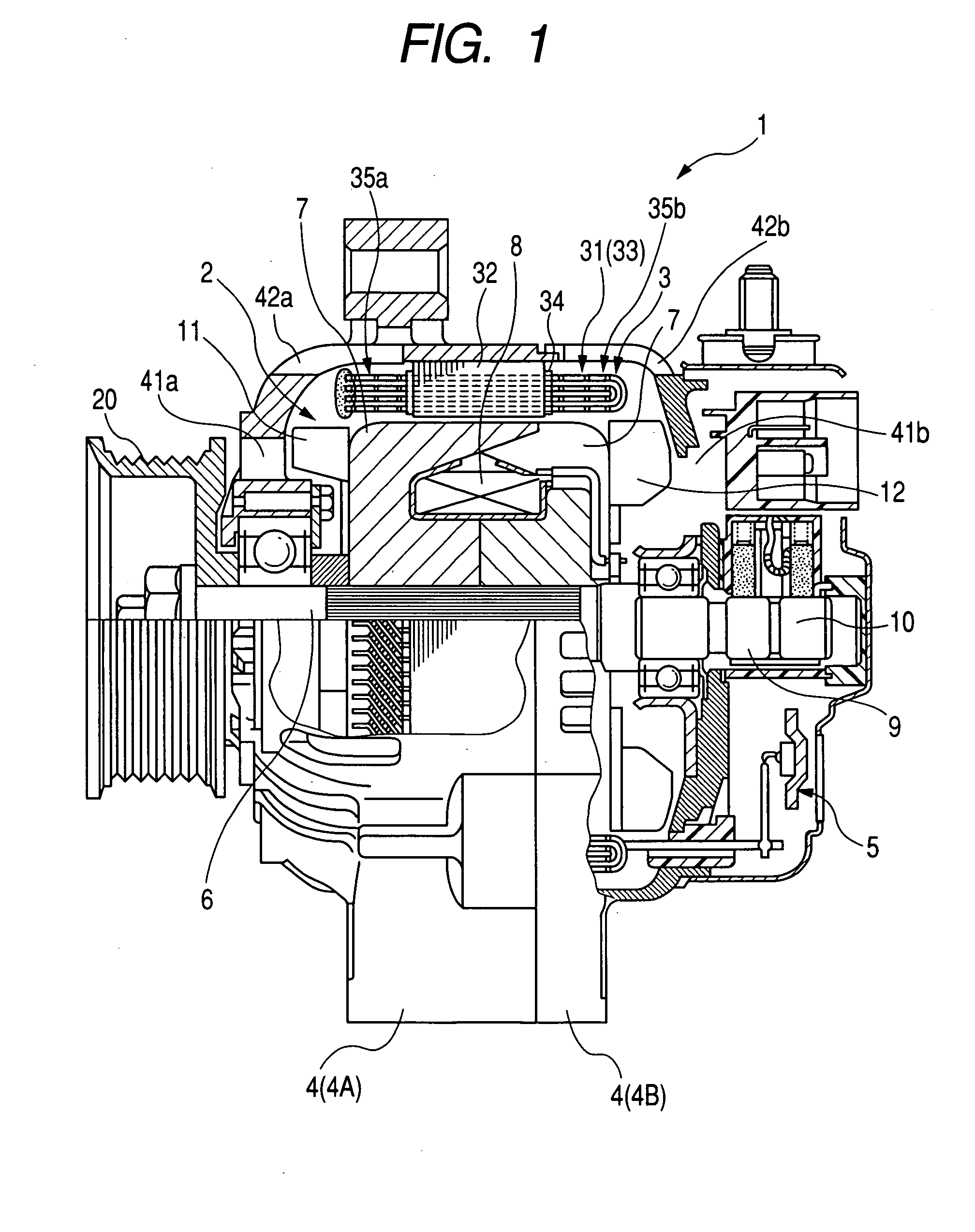
[0034]Referring to the drawings, in which like reference characters refer to like parts in several views, particularly to FIG. 1, there is illustrated an alternator 1 for vehicles, as an example of rotary electric machines.

[0035]The alternator 1 installed in, for example, an engine compartment of a vehicle includes a rotor 2, a stator 3, a frame 4, a rectifier 5, a voltage regulator (not shown), and so on.

[0036]The rotor 2 is attached to a rotary shaft 6 rotatably supported in the frame 4 by bearings so that it is disposed within the frame 4. One end of the rotary shaft 6 is linked to a pulley 20 such that the rotary shaft 6 is rotatably driven through the pulley 20 by an engine (not shown) installed in the engine compartment.

[0037]Specifically, the rotor 2 is composed of a Lundell type (claw pole) core 7. The pole core 7 has a pair of opposing circuit plates axiall...


PUM

PropertyMeasurementUnit
lengthaaaaaaaaaa
speedaaaaaaaaaa
sizeaaaaaaaaaa

Abstract

In a rotary electric machine, at least one of first and second ends of each conductor segment is at least partially joined to at least one of the first and second ends of a corresponding another one of the conductor segments to provide the stator winding including a plurality of joint portions of the plurality of conductor segments. An insulating film covers each of the conductor segments except for at least the joint portions of the stator winding. At least part of the insulating film of each of the conductor segments located close to a corresponding one of the joint portions contains an evaporatable component. An amount in ppm of the evaporatable component contained in the at least part of the insulating film is adjusted to be equal to or lower than 20000 ppm.

Description

CROSS REFERENCE TO RELATED APPLICATIONS[0001]This application is based on Japanese Patent Application 2006-233881 filed on Aug. 30, 2006. This application claims the benefit of priority from the Japanese Patent Application, so that the descriptions of which are all incorporated herein by reference.FIELD OF THE INVENTION[0002]The present invention relates to rotary electric machines installable in, for example, vehicles, such as passenger automobiles and trucks, and to stators for rotary electric machines.BACKGROUND OF THE INVENTION[0003]Rotary electric machines for vehicles, such as engine-driven alternators, need to have a high power output in order to achieve reduction in the idling engine speed of a vehicle as an environmental measure. They also need to be reduced in size and weight in order to implement weight reduction of a vehicle for improvement its fuel efficiency and reduction in the width of the engine compartment for finding room therein.[0004]For meeting the needs, some ...

Claims


Application Information

Patent Timeline
Patent Type & Authority Applications(United States)
IPC IPC(8): H02K3/32B23K35/02H02K1/16
CPCB23K35/02H02K15/12H02K15/0081H02K3/30
Inventor KOIKE, AKIHITO
Owner DENSO CORP
Features
  • R&D
  • Intellectual Property
  • Life Sciences
  • Materials
  • Tech Scout
  • Unparalleled Data Quality
  • Higher Quality Content
  • 60% Fewer Hallucinations
Learn More