Battery Characterization Technique

a battery and characterization technology, applied in secondary cell servicing/maintenance, instruments, therapy, etc., can solve the problems of damage to surrounding tissue, loss of recharging, and inability to meet the requirements of recharging, so as to reduce current flow

Inactive Publication Date: 2008-03-06
COCHLEAR LIMITED
View PDF25 Cites 32 Cited by
  • Summary
  • Abstract
  • Description
  • Claims
  • Application Information

AI Technical Summary

Benefits of technology

[0014]In accordance with another aspect of the invention, there is provided a system for a power supply for an electronic device, said power supply comprising: a rechargeable battery source configured for cyclical charging and discharging by said electronic device; a measuring circuit for measuring parametric data during said charging and discharging; an auxiliary power source being able to power said electronic device independently of said battery source; and a testing circuit for testing said measuring circuit for offset error; and a circuit for reducing current flow from said rechargeable battery to said device to a minimal value; wherein said testing circuit is enabled during said isolation of said rechargeable battery from said device.
[0015]In accordance with another aspect of the invention, there is provided a system for operating a rechargeable battery, said system comprising: current maintaining means for maintaining a predetermined current to said rechargeable battery until said rechargeable battery reaches a predetermined maximum voltage; voltage maintaining means for maintaining a predetermined voltage to said rechargeable battery until a predetermined minimum current is delivered to said rechargeable battery; determining means for determining a cyclical charge value delivered to said rechargeable battery by said current maintaining means and said voltage maintaining means during a cycle; and correction means for correcting said determining means when charge is not being delivered to said rechargeable battery, on the basis of said charge value.
[0016]In accordance with another aspect of the invention, there is provided an apparatus for characterizing a rechargeable battery, said apparatus comprising: a current limited source for delivering, during a first charging stage, a current flow to said rechargeable battery, until said rechargeable battery reaches a predetermined maximum voltage; a voltage limited source for maintaining, during a second charging stage, a substantially constant voltage to said rechargeable battery, until a current flow delivered to said rechargeable battery is below a predetermined minimum current; an integrator configured to integrate current flow delivered to said rechargeable battery during the first and second calibration stages; threshold detector means configured to signal a unit count of charge upon detection of a predetermined level of charge indicated by the output from said integrator; and correlator configured to correlate a total number of unit counts of charge during said first and second calibration stages with said predetermined maximum voltage and said predetermined minimum current.

Problems solved by technology

Another part of this power is converted into heat due to the internal resistance of the battery and, therefore, is lost for recharging.
Such power loss can lead to an impermissible temperature rise of the host device.
In those applications in which the battery is included in a component which is implanted in a patient, such temperature rise may also damage the surrounding tissue.
In particular, over years of operation, the capacity ratio of the positive and negative electrodes of a battery cell or cells shifts due to electrolyte loss and passivation and / or corrosion of the electrode surfaces.
As the gas pressure rises, the cell housing swells, which under certain circumstances can lead to destruction of the cell or the device in which the cell is housed.
However, voltage correlation techniques can be inaccurate due to variations in a battery's charging and discharging characteristics over its lifetime.
Clearly, this inaccuracy can lead to the undesirable consequences including those discussed above.
The main drawback to this method is its high processing requirement.
In many electronic devices, this increased processing burden is impractical because of the limited space and power constraints.
However, a drawback of the current integration approach is that inaccuracies can result from the inherent offsets in analog circuitry.
Compensation for these offsets has been shown to be more difficult to achieve for lower currents.

Method used


Image

  • Battery Characterization Technique
  • Battery Characterization Technique
  • Battery Characterization Technique

Examples


Embodiment Construction

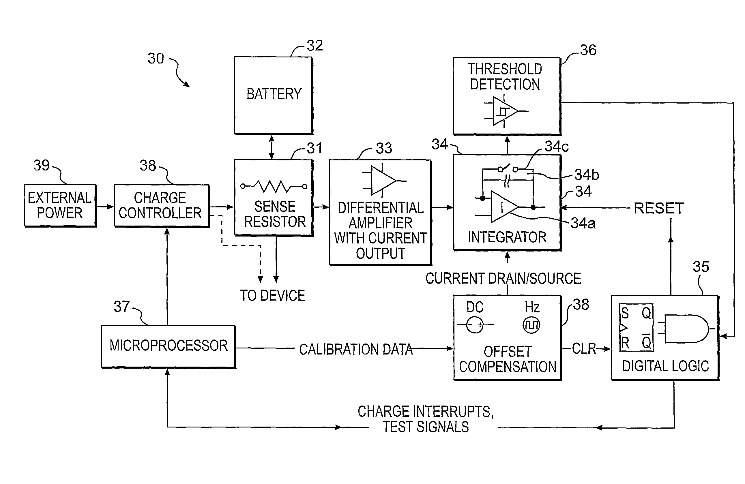
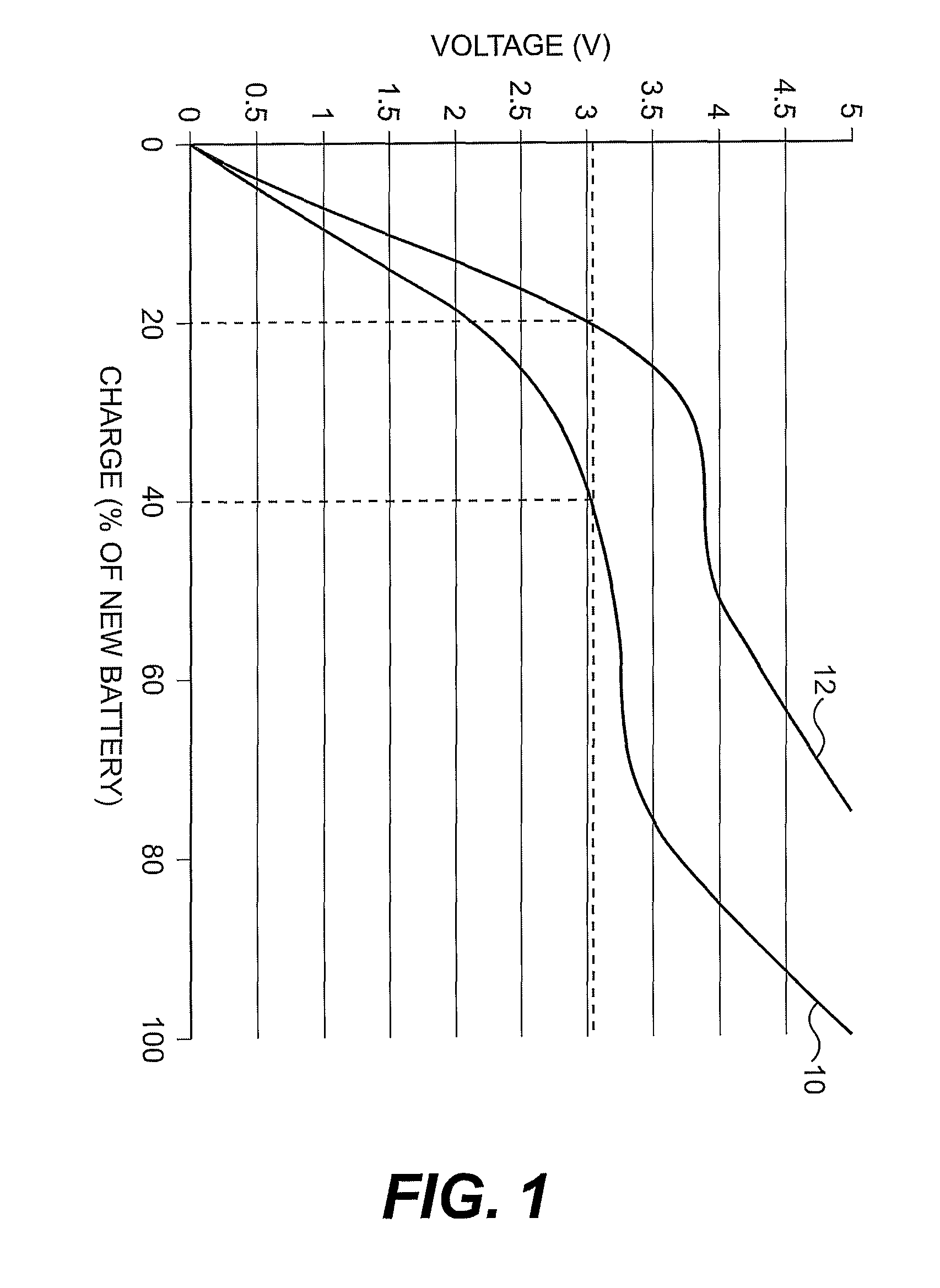
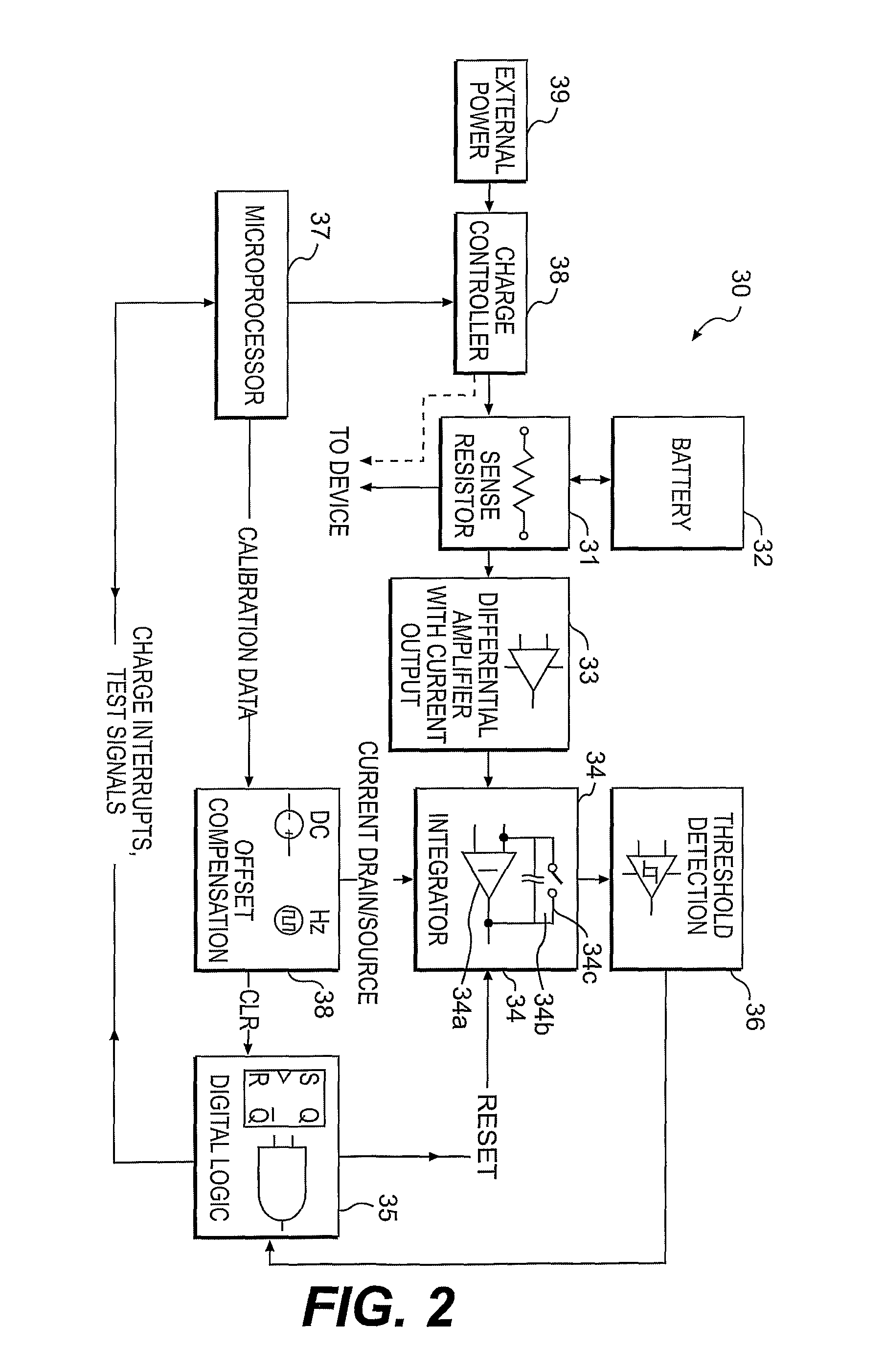
[0030]A starting point in developing a charge management regime for a rechargeable battery is to determine a method to measurably characterize the battery. This normally involves determining the remaining charge capacity in the battery, which can be ascertained in a number of ways. As earlier mentioned, the voltage of the battery can be used, in which case a measurement is regularly taken and an algorithm is implemented that attempts to estimate the amount of useful energy stored in the battery, and therefore may approximate the time remaining until the battery must be recharged.

[0031]However, such voltage-based calculations do not take into account the fact that the voltage depends on the chemistry, the current state the chemistry is in, i.e., ageing, the state of charge, and both, the load and the duration of load connection. Fading results in a reduced capacity, i.e., less charge can be stored in and retrieved from the battery. Ideally, a charge management algorithm using this vo...


PUM

PropertyMeasurementUnit
voltageaaaaaaaaaa
currentaaaaaaaaaa
voltageaaaaaaaaaa

Abstract

The present invention provides a system and method for operating a rechargeable battery, the system comprising: current maintaining device for maintaining a predetermined current to the rechargeable battery until the rechargeable battery reaches a predetermined maximum voltage; voltage maintaining device for maintaining a predetermined voltage to the rechargeable battery until a predetermined minimum current is delivered to the rechargeable battery; determining device for determining a cyclical charge value delivered to the rechargeable battery by the current maintaining device and the voltage maintaining device during a cycle; and a correction device for correcting the determining device when charge is not being delivered to the rechargeable battery, on the basis of the charge value.

Description

CROSS-REFERENCE TO RELATED APPLICATIONS[0001]This application makes reference to Australian Provisional Patent Application No. 2003903839, filed Jul. 24, 2003. Priority is claimed from this application for the present Application. In addition, this application is related to: U.S. Pat. No. 6,227,204, entitled “Device and process for charging of rechargeable batteries of implants,” filed May 14, 1999; U.S. patent application Ser. No. 09 / 654,731, entitled “Transcutaneous Power Optimization Circuit for a Cochlear™ Implant,” filed Sep. 5, 2000; U.S. patent application Ser. No. 10 / 257,170, entitled “Battery Monitor and Power Demand Adjuster,” filed Oct. 8, 2002; and U.S. patent application Ser. No. 09 / 962,898, entitled “Multiple Battery Management System” filed Sep. 25, 2001. The entire disclosure and contents of the above applications are hereby incorporated by reference.BACKGROUND[0002]1. Field of the Invention[0003]The present invention relates generally to batteries and, more particul...

Claims


Application Information

Patent Timeline
Patent Type & Authority Applications(United States)
IPC IPC(8): H02J7/00G01R31/36H04R25/00H01M10/44
CPCA61B2017/00734A61N1/36032H02J7/008H02J7/0075G01R31/3627G01R31/385H02J7/0069A61N1/36038H02J7/00714H02J7/007182H02J2310/23
Inventor ELIAS, BENJAMINNYGARD, TONY
Owner COCHLEAR LIMITED
Why Eureka
Try Eureka