Conductive thermal transfer ribbon

a thermal transfer ribbon and thermal transfer technology, applied in the direction of transfer patterning, thermal imaging, printing, etc., can solve the problems of unreliable or otherwise undesirable commercial scale production, high cost and production time of conventional means for forming electronic components on substrates, and high cost and production tim

Inactive Publication Date: 2008-03-06
INT IMAGING MATERIALS
View PDF99 Cites 21 Cited by
  • Summary
  • Abstract
  • Description
  • Claims
  • Application Information

AI Technical Summary

Benefits of technology

[0022]In accordance with this invention, there is provided a thermal transfer ribbon comprised of a support and an ink layer disposed above the support. The ink layer has a thickness of from about 0.1 to about 10 microns; it is comprised of at least 75 weight percent of particulate conductive metal material and from about 1 to about 25 weight percent of binder; and it has a surface resistivity of less than about 1,000,000 ohms per square. When the ink layer is transferred to a substrate durin...

Problems solved by technology

The conventional means for forming electronic components on substrates are relatively expensive.
Frequently these methods involve considerable capital costs and production time.”
Yet many of these methods are often unreliable or otherwise undesirable for commercial scale production.”
However, none of these efforts have been entirely successful.
It is believed that one major problem that has been encountered is that, in order to thermally transfer material from a thermal transfer ribbon to a substrate, the heat of the thermal printhead must change the material's state (such as, e.g., by melting or softening) so that the material can wet and adhere to the substrate and then release from the ribbon.
This material will be transferred by the heat from the thermal print head; however, it does not appear that the material so transferred will produce a printed layer with low enough electrical resistance for most printed electronics applications.
The solder material transferred by the “preferred circuit printer 20” (see column 3 of the patent and FIG. 2) is not very conductive and would not be acceptable for printing commercially acceptable conductive traces onto a substrate with conventional thermal printers.
This limits the use of solder ...

Method used


Image

  • Conductive thermal transfer ribbon
  • Conductive thermal transfer ribbon

Examples


example 1

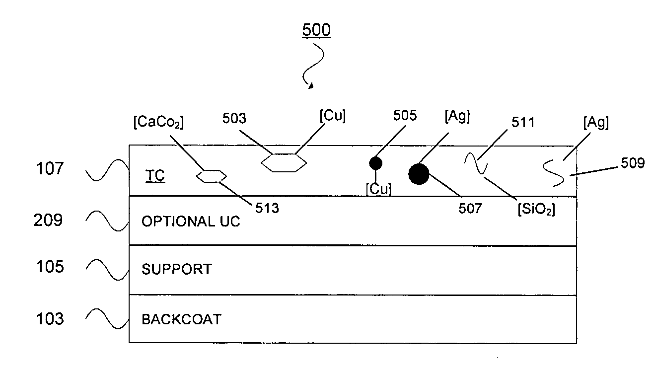
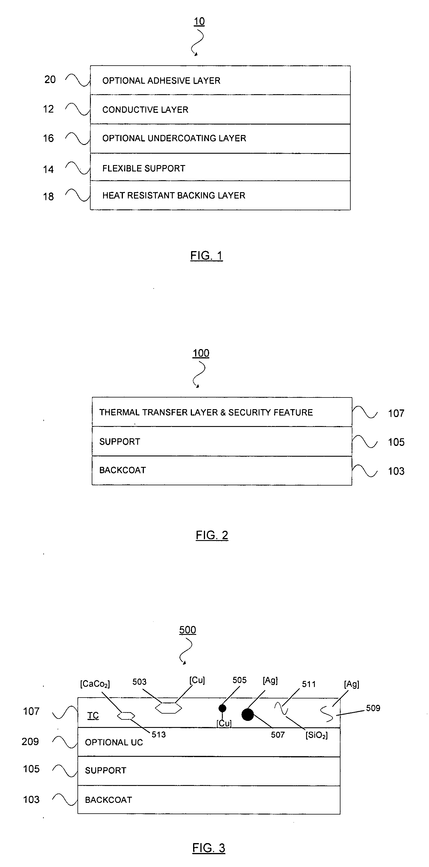
[0108]A thermal transfer ink was prepared by first heating 37.50 grams of solvent grade toluene (Chemcentral, Chicago, Ill.) to 70 C in a 2 oz glass jar on a combination hot plate and magnetic stirrer. A magnetic stir bar was then placed in the jar, and the stirrer was set to 300 rpm. 1.50 g of Unirez 2980 (a fatty acid dimer-based esteramide resin from Arizona Chemical, Jacksonville, Fla.), 0.19 g of Elvax 250 (an ethylvinylacetate copolymer from Chemcentral, Chicago, Ill.) and 0.18 g of Disperbyk 191 (a polyacrylate copolymer with pigment acidic groups from Dar-Tech, Cleveland, Ohio) were added to the solvent thus prepared, and the lid of the jar was set loosely on the jar to retard solvent evaporation. This mixture was left under heat and agitation for 10 minutes until the solution was homogenous. This solution was of a clear pale yellow color. The solution was then transferred to a half-pint paint can, and 35.63 g of S2-80 (spherical 80 nanometer silver particles from NanoDynami...

example 2

[0111]The procedure of Example 1 was substantially followed, with the exception that the Uni-Rez 2980 and the Elvacs 250 were replaced with 1.86 grams of Synthetic Resin AP (a acetophenone-formaldehyde-condensation resin from Dar-Tech, Cleveland, Ohio), 0.20 grams of Disperbyk 111 were used, 39.19 grams of the S280 silver material were used, and the coating weight for the conductive ink layer was 7.27 grams per square meter. The resulting print had a brownish color. The thickness of the printed ink was measured via scanning electron microscope to be 1.5 microns. Surface resistivity of the unprinted ribbon was in excess of 1,000,000 ohms per square. The resistivity of the printed image was 869,760 ohms / square. A soft cloth was then used to gently polish the print which turned a lustrous silver color. Surface resistivity was then measured on the polished print, and it was 3.00 ohms / square.

example 3

[0112]The procedure of Example 1 was substantially followed, with the exception that the ink used was comprised of 35.63 grams of C1-500 (spherical 0.50 micron copper particles obtained from NanoDynamics, Buffalo, N.Y.) in place of the S280 silver particles. The thermal transfer ink was coated at 7.38 grams per square meter. Thermally transferred prints from this ink developed no conductivity with the multimeter reading “overflow”; indicating an open circuit.

[0113]It was unexpected that copper, which has a conductivity similar to that of silver, produced a product with such poor conductivity.


PUM

PropertyMeasurementUnit
Temperatureaaaaaaaaaa
Lengthaaaaaaaaaa
Lengthaaaaaaaaaa

Abstract

A thermal transfer ribbon comprised of a support and an ink layer disposed above the support. The ink layer has a thickness of from about 0.1 to about 10 microns; it contains at least 75 weight percent of particulate conductive metal material and from about 1 to about 25 weight percent of binder; and it has a surface resistivity of less than about 1,000,000 ohms per square. When the ink layer is transferred to a substrate, the surface resistivity of the transferred ink is less than 100 ohms per square when printed onto a flexible substrate at a printing speed of 2 centimeters per second and a printing energy of 7.6 joules per square centimeter. The particulate conductive metal preferably contains a noble metal and has a melting point of at least 800 degrees Celsius and a particle size such that least about 95 weight percent of its particles are smaller than 50 microns.

Description

CROSS-REFERENCE TO RELATED PATENT APPLICATIONS[0001]This patent application claims priority based upon U.S. patent application 60 / 840,732, filed on Aug. 29, 2006. The entire disclosure of this provisional patent application is hereby incorporated by reference into this specification.FIELD OF THE INVENTION[0002]A conductive thermal transfer ribbon adapted to print an electrically conductive pathway onto a substrate.BACKGROUND OF THE INVENTION[0003]The conventional means for forming electronic components on substrates are relatively expensive. Some of these prior art means were discussed in U.S. Pat. No. 7,062,848 of Alfred I-Tsung Pan et al. In column 1 of this patent, it was disclosed that: “Formation of electronic components and other conductive paths can be accomplished using a wide variety of known methods. Typical methods for manufacturing printed circuits include print and etch, screen printing, and photo-resist methods. Frequently these methods involve considerable capital cos...

Claims


Application Information

Patent Timeline
IPC IPC(8): B41M5/40
CPCB41M5/3825H05K3/046H05K2203/1105H05K2203/0528H05K3/207
Inventor HARRISON, DANIEL J.GEDDES, PAMELA A.BALLING, BERNARDBERUBE, GREGORY
Owner INT IMAGING MATERIALS
Why Eureka
Try Eureka