Discharge Lamp Device
a discharge lamp and discharge tube technology, applied in the direction of discharge tube luminescnet screens, lighting and heating apparatus, instruments, etc., can solve the problems of poor luminous flux startup characteristic, undesirable, and the desire for light source devices that do not use mercury, and achieve the effect of reducing cost, reducing size and improving efficiency
- Summary
- Abstract
- Description
- Claims
- Application Information
AI Technical Summary
Benefits of technology
Problems solved by technology
Method used
Image
Examples
embodiment 1
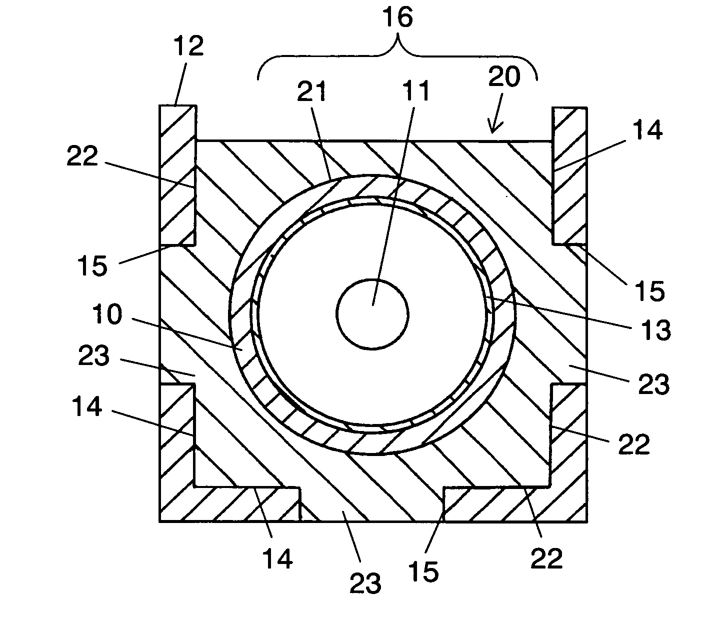
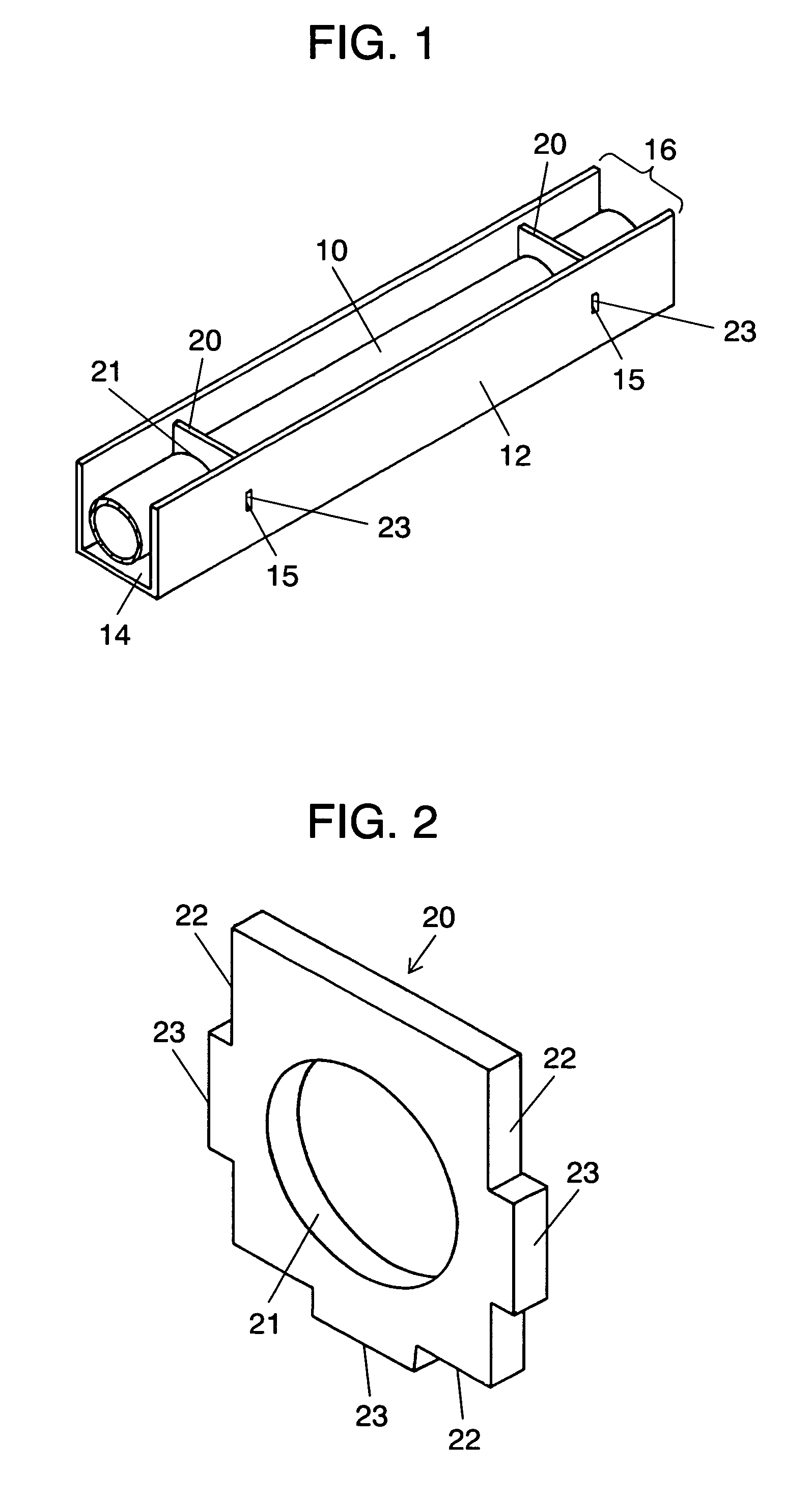
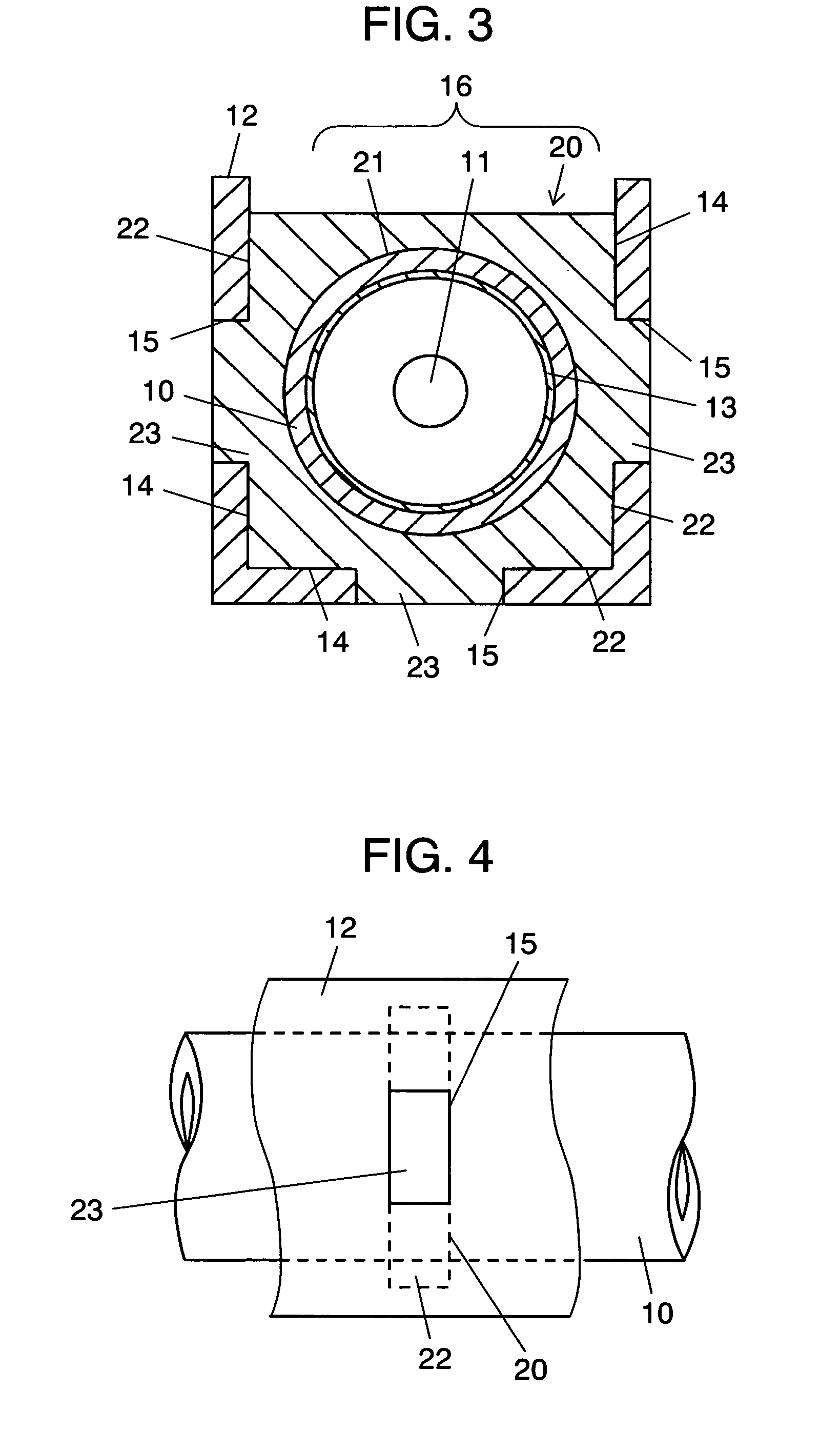
[0055]Embodiment 1 of a discharge lamp device according to the present invention will be described with reference to FIG. 1 to FIG. 6. The discharge lamp device according to Embodiment 1 includes airtight container 10 in which both end sections of a glass bulb (not shown) are sealed. The interior of airtight container 10 is filled with discharge medium mainly including noble gas. One end section or both end sections of airtight container 10 include(s) first electrode 11. Insulating holder 2 is externally attached to airtight container 10 at one or a plurality position(s) of airtight container 10 (two positions in FIG. 1). Holder 20 is attached with second electrode 12.
[0056]Airtight container 10 is made of material such as glass (borosilicate glass, silica glass, soda glass, lead glass), organic matter (e.g., acryl), or other translucent materials. Airtight container 10 basically has a straight pipe-like shape but also may have an L-like shape, a U-like shape, or a rectangular shape...
embodiment 2
[0070]Embodiment 2 will be described with reference to FIG. 7 and FIG. 8. Embodiment 2 is characterized in that a relation between thickness a of holder 20 in a longitudinal direction of airtight container 10 and width b of protrusion 23 in the longitudinal direction of airtight container 10 is determined to be a>b. Specifically, holder 20 has a thickness that is thicker than a width of protrusion 23.
[0071]When a user holds a liquid crystal display using the discharge lamp device of the present invention as a backlight by hands, a risk may be caused where the discharge lamp device receives pressure from a side to deform holder 20 and thus a distance between airtight container 10 and second electrode 12 is changed. Another risk may be caused where dust may come into second electrode 12 via a clearance between protrusion 23 and fitting hole 15 formed in second electrode 12.
[0072]Thus, the structure according to Embodiment 2 can minimize the deformation of holder 20 even when being sub...
embodiment 3
[0073]Embodiment 3 will be described with reference to FIG. 9 and FIG. 10. Embodiment 3 is characterized in that holder 20 is structured as described below. Specifically, length a of holder 20 in the longitudinal direction of airtight container 10 is determined such that a relation between length a1 at a side from which airtight container 10 emits light and length a2 at a side at which second electrode 12 is provided and which is opposed to opening 16 is a12. Specifically, holder 20 is formed to have an almost trapezoidal shape when seen from the front and holder 20 has a thickness that is reduced in a direction along which light is emitted. A relation between a2 and width b of protrusion 23 of holder 20 is determined to be a2>b from the viewpoint of securing the rigidity of holder 20. A relation between a1 and b is determined to be a110.
[0074]The structure as described above provides not only the function and effect of Embodiment 2 but also forms holder 20 so that the thickness of ...
PUM
 Abstract
Description
Claims
Application Information
 - R&D
- Intellectual Property
- Life Sciences
- Materials
- Tech Scout
- Unparalleled Data Quality
- Higher Quality Content
- 60% Fewer Hallucinations
Browse by: Latest US Patents, China's latest patents, Technical Efficacy Thesaurus, Application Domain, Technology Topic, Popular Technical Reports.
© 2025 PatSnap. All rights reserved.Legal|Privacy policy|Modern Slavery Act Transparency Statement|Sitemap|About US| Contact US: help@patsnap.com


