RF Coil and MRI System

Inactive Publication Date: 2008-03-13
HITACHI LTD
View PDF8 Cites 25 Cited by
  • Summary
  • Abstract
  • Description
  • Claims
  • Application Information

AI Technical Summary

Benefits of technology

[0018]According to the invention, an RF coil which can transceive a circularly-polarized magnetic field having high Signal-To-Noise ratio and uniformity can be provided as in the case where power is supplied by the QD method with one feeding port. Therefore, since there is one less feeding port compared with the QD method, in the case of a transmit coil, the divider and phase shifter are unnecessary, and in the case of a receive coil, the combiner and phase shifter are unnecessary, while the number of the parts which form the transceiver system i

Problems solved by technology

Since two sets of wiring must be connected for one coil, the construction becomes complex and the number of parts increases, so adjustment is complicated and manufacturing costs increase.
There is the problem that, due to phase shifts in the divider, combiner and phase shifter and mechanical distortion in the coils, orthogonality decrease

Method used


Image

  • RF Coil and MRI System
  • RF Coil and MRI System
  • RF Coil and MRI System

Examples


first embodiment

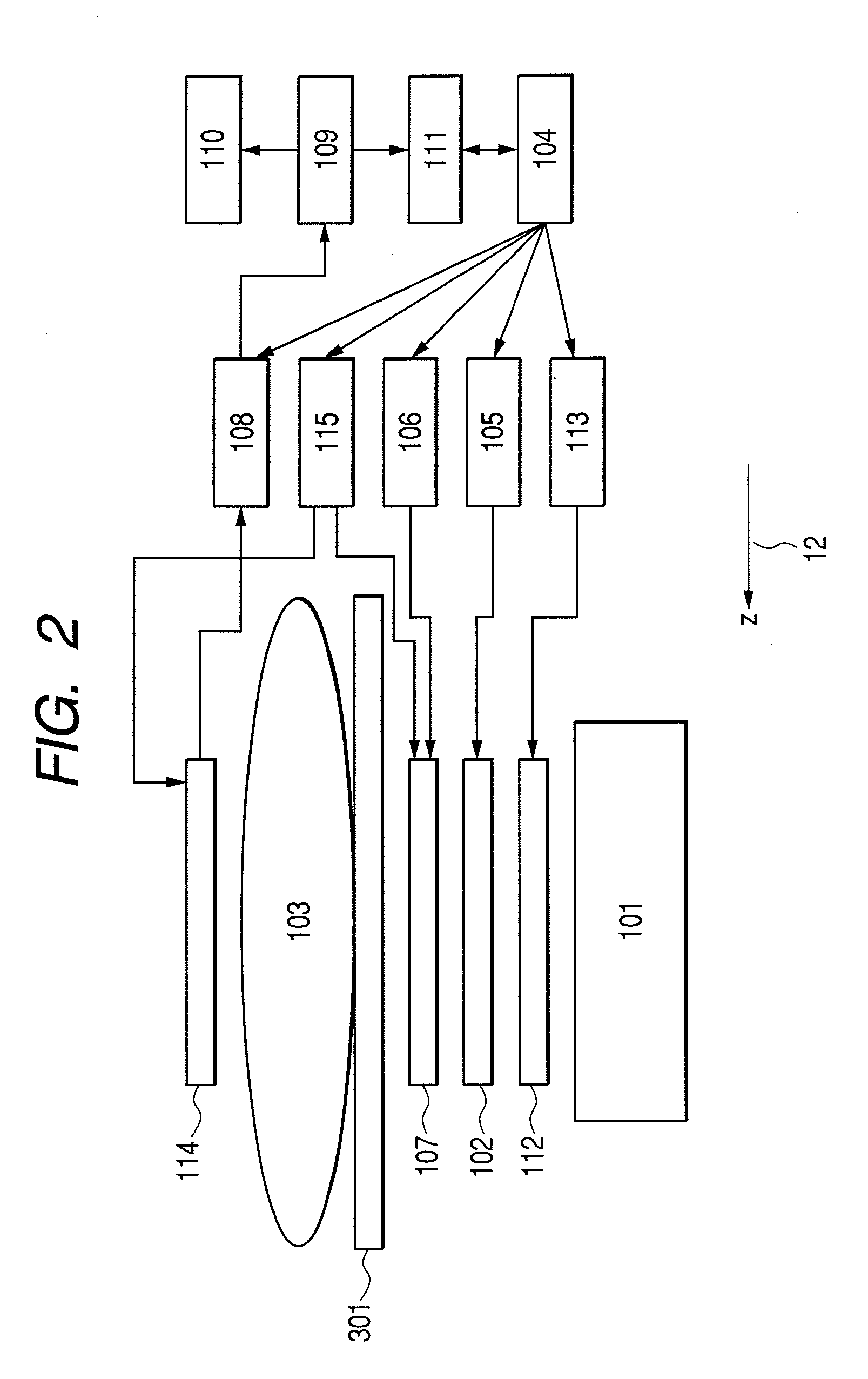
[0056]A magnetic resonance imaging apparatus according to the first embodiment will now be described. FIG. 2 is a block diagram showing the main features of the construction. Identical elements to those in FIG. 1 are denoted by identical symbols. The magnetic resonance imaging apparatus shown in the diagram includes the magnet 101, a gradient coil 102, a shim coil 112 for adjusting the uniformity of the static magnetic field, a sequencer 104 which controls the field application sequence, a transmit RF coil 107 which generates a RF magnetic field, and a receive RF coil 114 which detects a magnetic resonance signal. The gradient coil 102 and shim coil 112 are connected to a gradient coil power supply 105 and shim coil power supply 113, respectively. The transmit RF coil 107 is connected to a RF magnetic field generator 106 and magnetic decoupling driver 115, and the receive RF coil 114 is connected to a receiver 108 and the magnetic decoupling driver 115. The transmit RF coil 107 and ...

second embodiment

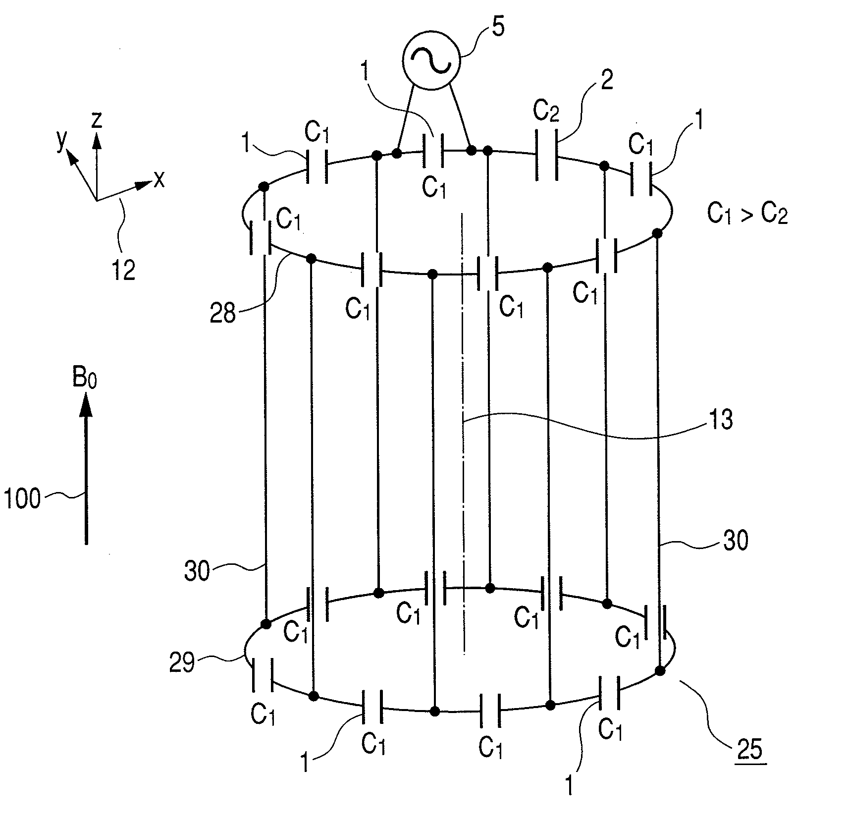
[0110]FIG. 23 shows the construction of a birdcage-type circularly-polarized RF coil 25 according to a second embodiment of the invention. In the birdcage-type circularly-polarized RF coil 25, as shown in FIG. 23A, the 2 loop conductors 28, 29 are disposed so that the center axes of the loops are parallel and substantially parallel to the z axis of the axes 12, and plural (in FIG. 23A, 8) linear conductors 30 which are substantially linear and substantially parallel to the z axis of the axes 12, are connected thereto. At this time, the plural linear conductors 30 are disposed at equidistant intervals. It is assumed that the direction of the z axis of the axes 12 is identical to the orientation of the static magnetic field 100 generated by the magnet 101 of the magnetic resonance imaging apparatus. In other words, the central axis of the loops is substantially identical to the orientation of the static magnetic field generated by the magnet of the magnetic resonance imaging apparatus...

third embodiment

[0137]A TEM-type circularly-polarized RF coil 31 which is a third embodiment of this invention, will now be described. This RF coil may also be used as a transmit or receive RF coil. FIG. 30 is a diagram showing the construction of this coil. In this TEM-type circularly-polarized RF coil 31, as shown in FIG. 30A, plural (in FIG. 30A, 8) substantially linear conductors 47, which are substantially parallel to the axis of a cylinder conductor 46, are disposed at substantially equidistant intervals in the circumferential direction at a constant distance from the inner surface of the cylinder conductor 46, and their two ends are connected to the inside of the cylinder conductor 46 via connecting conductors. Plural first capacitors 1 and a second capacitor 2 are inserted into the connecting conductors connecting the linear conductors 47 to the cylinder conductor 46, and the feeding port 5 is disposed in one of the first capacitors 1 so that this coil resonates at the magnetic resonance fr...


PUM


Abstract

In an MRI apparatus, an RF coil is provided which can generate or detect a circularly-polarized magnetic field with one feeding port, and which can radiate highly efficient, highly homogeneous electromagnetic waves and detect a highly sensitive, highly homogeneous magnetic resonance signal. For this purpose, the coil has a cylindrical shape, one feeding port which exchanges signals, plural first capacitors disposed at circumferential positions in at least one cross-section effectively orthogonal to the direction of the static magnetic field, and at least one second capacitor. In this RF coil, in which a static magnetic field is applied in essentially an identical direction to the direction of the central axis of the cylindrical shape, a second capacitor having a smaller capacity than the capacity of the first capacitor, is disposed at a position from 22.5° to 67.5° or 202.5° to 247.5° in a clockwise direction with respect to the center of the cylindrical shape from the feeding port in a cross-section viewed from a direction passing through the static magnetic field.

Description

CLAIM OF PRIORITY[0001]The present application claims priority from Japanese application JP 2006-247478 filed on Sep. 13, 2006, the content of which is hereby incorporated by reference into this application.FIELD OF THE INVENTION[0002]The present invention relates to MRI (magnetic resonance imaging), and more particularly to a RF coil for transmitting electromagnetic waves and detecting a magnetic resonance signal.BACKGROUND OF THE INVENTION[0003]A magnetic resonance imaging apparatus is a medical imaging and diagnostic device which generates a magnetic resonance with atomic nuclei in an arbitrary cross-section passing horizontally through a test subject, and obtaining a tomogram in that cross-section from the magnetic resonance signal which is generated.[0004]In order to obtain an image of high precision and high resolution, various parts of magnetic resonance imaging apparatus are being improved. In particular, in a RF coil (RF coil) which performs irradiation of electromagnetic w...

Claims


Application Information

Patent Timeline
IPC IPC(8): G01R33/34
CPCG01R33/34076G01R33/3453G01R33/3678G01R33/3635G01R33/3628
Inventor SOUTOME, YOSHIHISAHABARA, HIDETAOCHI, HISAAKI
Owner HITACHI LTD
Why Eureka
Try Eureka