
System and method for implementing a phase detector to support a data transmission procedure

Inactive Publication Date: 2008-03-13
SONY CORP
View PDF21 Cites 16 Cited by
  • Summary
  • Abstract
  • Description
  • Claims
  • Application Information

AI Technical Summary

Benefits of technology

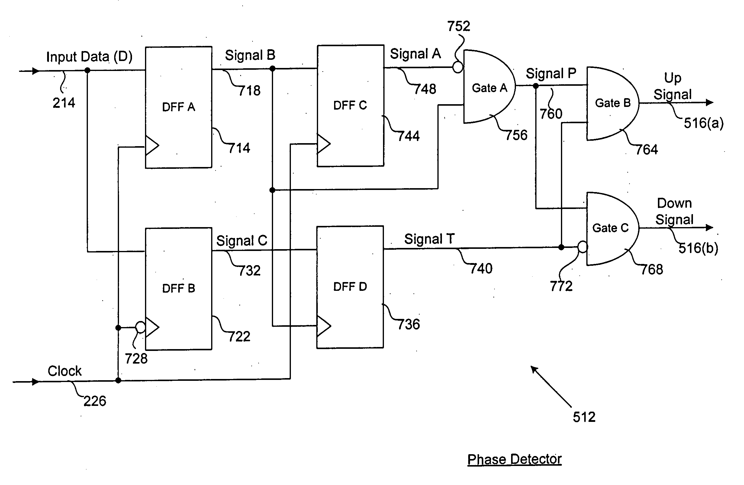
[0014]In the present embodiment, edge detection signal P is applied to first inputs of both up gate B and down gate C. In addition, up gate B receives lead / lag indicator signal T on a second input. In response, up gate B outputs an up signal for potentially adjusting (when active) the clock signal. Furthermore, lead / lag indicator signal T is inverted by the third inverter, and is then provided to a second input of down gate C. In response, down gate C outputs a down signal for potentially adjusting (when active) the clock signal. For at least the foregoing reasons, the present invention therefore provides an improved system and method for effectively implementing a phase detector to support a data transmission procedure.

Problems solved by technology

However, effectively implementing data transfer systems may create substantial challenges for system designers.
For example, enhanced demands for increased system functionality and performance may require more system processing power and require additional hardware resources.
An increase in processing or hardware requirements may also result in a corresponding detrimental economic impact due to increased production costs and operational inefficiencies.

Method used


Image

  • System and method for implementing a phase detector to support a data transmission procedure
  • System and method for implementing a phase detector to support a data transmission procedure
  • System and method for implementing a phase detector to support a data transmission procedure

Examples


Embodiment Construction

[0024]The present invention relates to an improvement in data transmission systems. The following description is presented to enable one of ordinary skill in the art to make and use the invention, and is provided in the context of a patent application and its requirements. Various modifications to the disclosed embodiments will be readily apparent to those skilled in the art, and the generic principles herein may be applied to other embodiments. Thus, the present invention is not intended to be limited to the embodiments shown, but is to be accorded the widest scope consistent with the principles and features described herein.

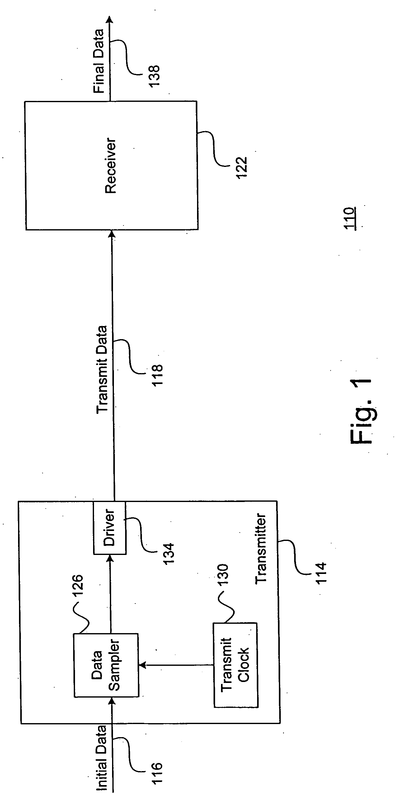
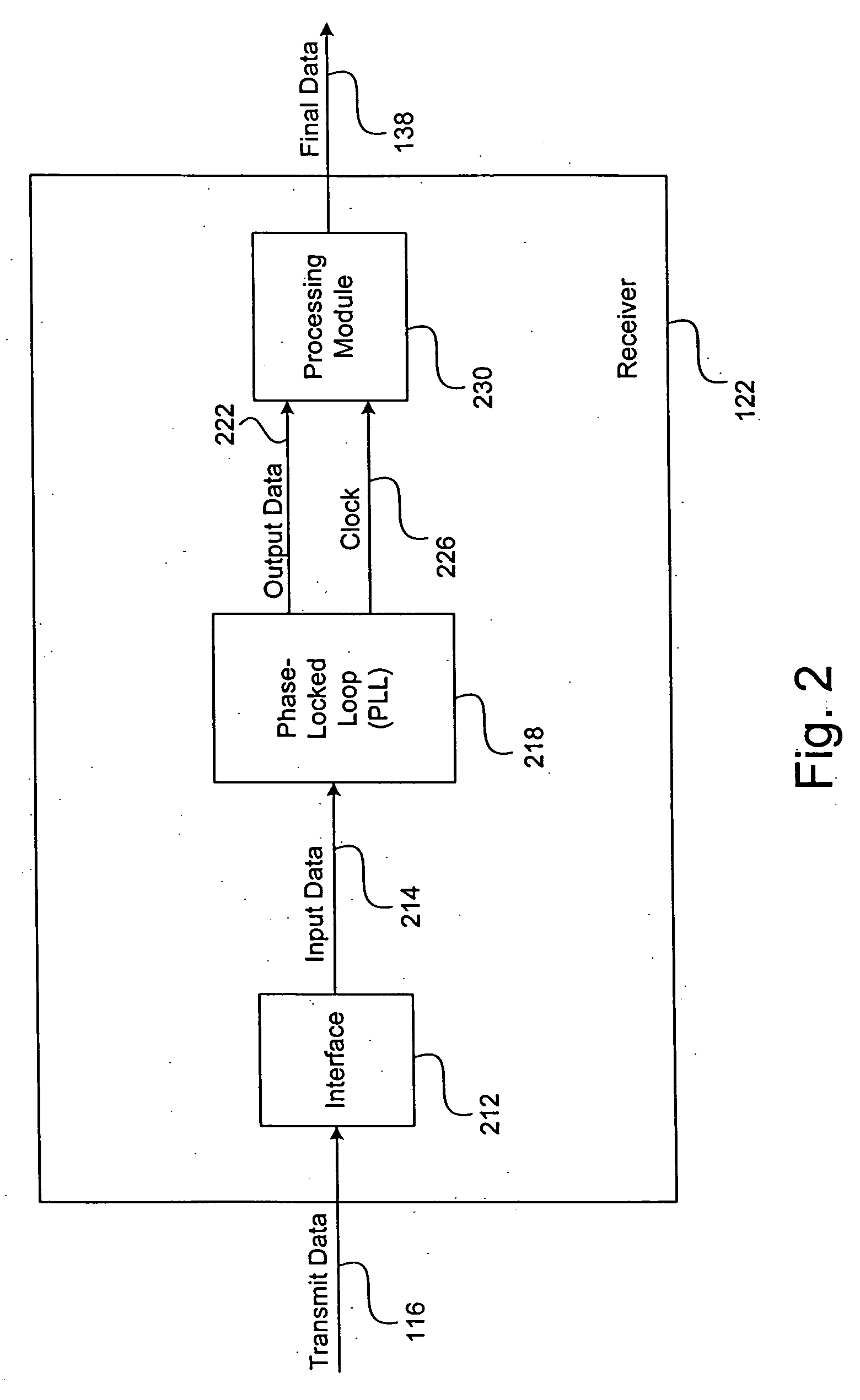
[0025]The present invention is described herein as a system and method for effectively supporting a data transmission procedure, and includes a phase-locked loop with a phase detector that compares a clock signal and input data to generate a phase error signal for adjusting the clock signal that is generated from a voltage-controlled oscillator. The phase detec...


PUM


Abstract

A system and method for effectively supporting a data transmission procedure includes a phase-locked loop with a phase detector that compares a clock signal and input data to generate a phase error signal for adjusting the clock signal that is generated from a voltage-controlled oscillator. The phase detector includes a positive-edge detector circuit that generates an edge detection signal P to indicate whether data transitions are present in the input data. The phase detector also includes a lead / lag indicator circuit that generates a lead / lag indicator signal T to indicate whether the clock signal is early or late with respect to the input data.

Description

CROSS-REFERENCE TO RELATED APPLICATION[0001]This Application claims priority in U.S. Provisional Patent Application No. 60 / 844,588 entitled “Gbps Transceiver Core Using A Tri-State Binary Phase Detector With 100 ps Gated Digital Output,” that was filed on Sep. 13, 2006. The foregoing related Application is commonly owned, and is hereby incorporated by reference.BACKGROUND SECTION[0002]1. Field of the Invention[0003]This invention relates generally to techniques for transferring electronic information, and relates more particularly to a system and method for effectively implementing a phase detector to support a data transmission procedure.[0004]2. Description of the Background Art[0005]Implementing effective methods for transferring electronic information is a significant consideration for designers and manufacturers of contemporary electronic systems. However, effectively implementing data transfer systems may create substantial challenges for system designers. For example, enhance...

Claims


Application Information

Patent Timeline
IPC IPC(8): H03D3/24
CPCH03D13/004
Inventor CHATWIN, JEREMY
Owner SONY CORP
Learn More