Image processing method, image processing apparatus and image pickup apparatus and display apparatus suitable for the application of image processing method

a technology of image processing and image pickup, which is applied in the direction of image enhancement, instruments, television systems, etc., can solve the problems of not exerting an influence on the real-time processing done by image processing, difficult to avoid completely the influence of distortion, and the inability to reduce so as to reduce the capacity of a necessary memory, memory capacity, and the effect of reducing the number of required distortion correction parameters

Inactive Publication Date: 2008-03-13
SONY CORP
View PDF5 Cites 9 Cited by
  • Summary
  • Abstract
  • Description
  • Claims
  • Application Information

AI Technical Summary

Benefits of technology

[0052] According to the present invention, the lattice position determined by lattice dividing means is used and data necessary for calculation is compressed by using crossing positions of lattice and data obtained from parameter deriving means. Thus, a capacity of a necessary memory can be reduced. According to the present invention, assuming that the picture is divided in the x direction by m and also divided in the y direction by n, then memory capacity reduction effect of 3n*m+n+m−1 can be achieved.
[0053] Specifically, assuming that the picture is divided by polynomial of degree k, divided in the x direction by m and also divided in the y direction by n, then as shown in FIG. 11, we can have the divided lattice line n*(m+1)+m*(n+1). In this case, according to the present invention, the number of required distortion correction parameters can be reduced from the related-art (k+1){n*(m+1)+m*(n+1)} to the inventive (n+1)*(m+1)+(k−1){n*(m+1)+m*(n+1)}, and hence the memory capacity reduction effect of 3n*m+n+m−1 can be achieved.

Problems solved by technology

So far distortion has been caused in an image picked up by a video camera, a digital still camera or a silver halide camera by influences of distortion characteristics of an image pickup lens.
While such distortions are inconspicuous in highly-accurate and high-performance lenses, when an inexpensive lens or an optical zoom lens is in use, it is difficult to avoid influences exerted by distortions completely.
Although calculation and encoding in the correction parameter deriving unit 800 become calculations having very large calculation loads, such calculations may be executed separately by other suitable means such as a personal computer, and hence may not exert an influence upon real-time processing done by the image processing apparatus 100.
However, the above-mentioned signal processing apparatus encounters with problems in which a memory capacity of a memory is large, real-time processing being difficult.
Specifically, since the memory capacity is large, the scale of hardware is large.
Hence, reduction of power consumption is difficult and the related-art signal processing apparatus is costly.
Furthermore, the related-art signal processing apparatus cannot cope with the case in which characteristics of distortion of an image pickup lens are changed such as when the position of optical zoom is fluctuated or when a lens is exchanged.

Method used


Image

  • Image processing method, image processing apparatus and image pickup apparatus and display apparatus suitable for the application of image processing method
  • Image processing method, image processing apparatus and image pickup apparatus and display apparatus suitable for the application of image processing method
  • Image processing method, image processing apparatus and image pickup apparatus and display apparatus suitable for the application of image processing method

Examples


Embodiment Construction

[0100] An embodiment of the present invention will be described below in detail with reference to the drawings. In the drawings, identical reference numerals denote identical elements and parts.

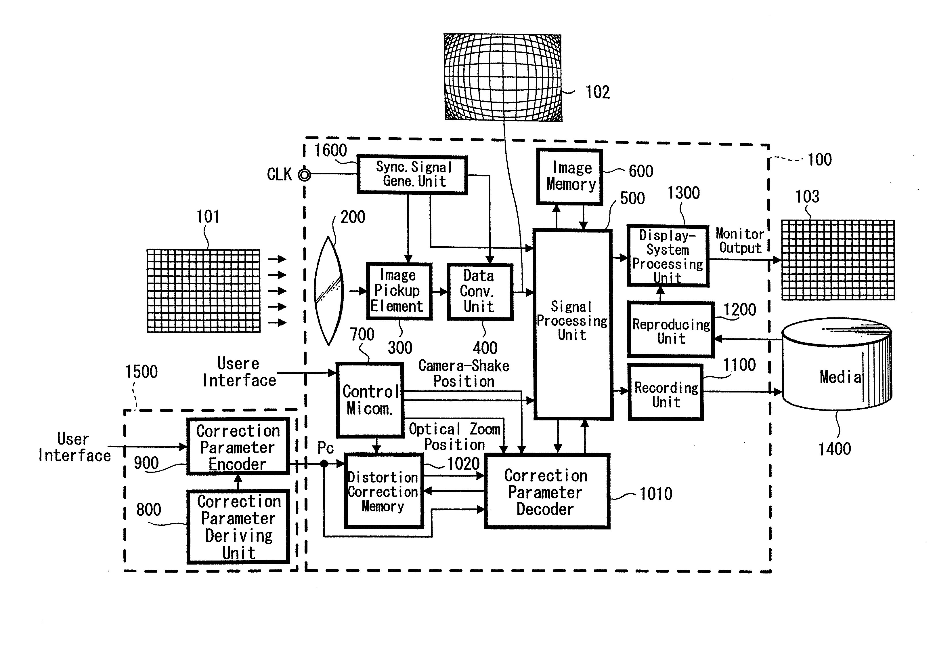
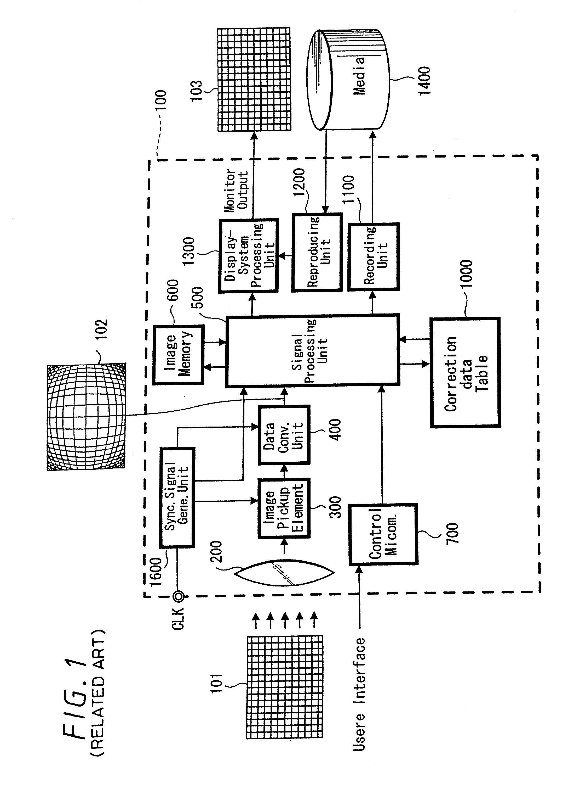
[0101]FIG. 12 is a block diagram showing an arrangement of an image processing system according to an embodiment of the present invention. The arrangement of the hardware shown in FIG. 12 is exactly the same as the arrangement of the image processing system that the assignee of the present invention has previously proposed (see FIG. 3). While the image processing apparatus according to the present invention is realized by mainly software, this software comprising the image processing apparatus of the present invention will be described below in the form of a functional block diagram for simplicity.

[0102] As shown in FIG. 12, the image processing system according to this embodiment comprises the image processing apparatus 100, the pre-processing apparatus 1500 and the media 1400. The image p...


PUM


Abstract

A lattice dividing unit determines lattice lines to divide parameters of all points of a picture at every division and supplies distortion correction parameters (distortion correction coordinates) on the lattice points to a distortion correction memory (not shown). A polynomial of degree n coefficient deriving unit expresses all distortion correction coordinates on each lattice line in the form of a function relative to positions on lattice lines and approximates the distortion correction coordinates by desired division polynomial of degree n. Further, a sample point deriving unit compresses distortion correction parameters based upon the division polynomial of degree n obtained from the polynomial of degree n coefficient deriving unit. In the derived division polynomial of degree n, internal points which result from dividing both ends of the division polynomial of degree n by n is supplied to the distortion correction memory as new distortion correction parameters (approximated distortion correction coordinates). Thus, a memory capacity of a required memory can be reduced in the image processing for correcting distortion of an image.

Description

CROSS-REFERENCE TO RELATED APPLICATIONS [0001] The present application is a division of application Ser. No. 10 / 760,674, filed on Jan. 21, 2004, which claims priority to Japanese Application No. JP 2003-022642, filed on Jan. 30, 2003. The entire contents of Ser. No. 10 / 760,674 is incorporated herein by reference.BACKGROUND OF THE INVENTION [0002] 1. Field of the Invention [0003] The present invention relates to an image processing method, an image processing apparatus for use with a video camera, a digital still camera and a silver halide camera and an image pickup apparatus and a display apparatus suitable for the application of this image processing method. [0004] 2. Description of the Related Art [0005] So far distortion has been caused in an image picked up by a video camera, a digital still camera or a silver halide camera by influences of distortion characteristics of an image pickup lens. While such distortions are inconspicuous in highly-accurate and high-performance lenses,...

Claims


Application Information

Patent Timeline
Patent Type & Authority Applications(United States)
IPC IPC(8): G06K9/36G06T3/00H04N1/387H04N1/40H04N5/228
CPCG06T3/0018H04N5/3572H04N5/217G06T5/006H04N23/81H04N25/61
Inventor NOSE, ATSUSHIAOYAMA, KOJIKURATA, TOHRUWADA, KIMITAKA
Owner SONY CORP
Why Eureka
Try Eureka