
System and method for providing wireless over a passive optical network (PON)

a passive optical network and wireless technology, applied in the field of network systems, can solve the problems of interfaces and/or equipment between base stations and central offices, requiring costly implementation, and expensive to purchase and maintain, and achieves excellent complements, simplifying network management, and maximizing the utilization of existing network infrastructure.

Active Publication Date: 2008-03-13
NEC CORP
View PDF12 Cites 185 Cited by
  • Summary
  • Abstract
  • Description
  • Claims
  • Application Information

AI Technical Summary

Benefits of technology

The patent text describes a solution for integrating wireless access technologies with optical access networks in a cost-effective way. The solution maximizes the use of existing network infrastructure and simplifies network management. The wireless over PON network takes advantage of the PON infrastructure to extend the service areas and deliver broadband wireless services to portable and mobile customers as well as customers that cannot be economically reached by wireline connections. The wireless base station takes advantage of a Gigabit PON infrastructure to extend an antenna to a remote site, and the multiplexing schemes may include WDM, SCM, and TDM. The network system and method simultaneously provide wireline and wireless services by integrating a wireless base station at a central office and coupling a passive optical network to the wireless base station to extend the wireless signal to a remote site. The technical effects of the patent text include cost-effective implementation of a heterogeneous network that integrates optical and wireless access networks, efficient utilization of network resources, and reduction of management and maintenance costs.

Problems solved by technology

Such solutions require dedicated fiber links for each base station; thus requiring costly implementation.
Note although the microwave / wireless point-to-point links eliminate the dedicated wireline connection) additional microwave / wireless equipment is needed, which is expensive to purchase and maintain.
In addition, the interfaces and / or equipment between the base stations and the central office increase management costs.
This solution needs to allocate certain wireline bandwidth to carry wireless services; thus, it is often difficult to realize in heavy-traffic scenarios.
Dedicated links or cascaded connections are not economic.

Method used


Image

  • System and method for providing wireless over a passive optical network (PON)
  • System and method for providing wireless over a passive optical network (PON)
  • System and method for providing wireless over a passive optical network (PON)

Examples


Embodiment Construction

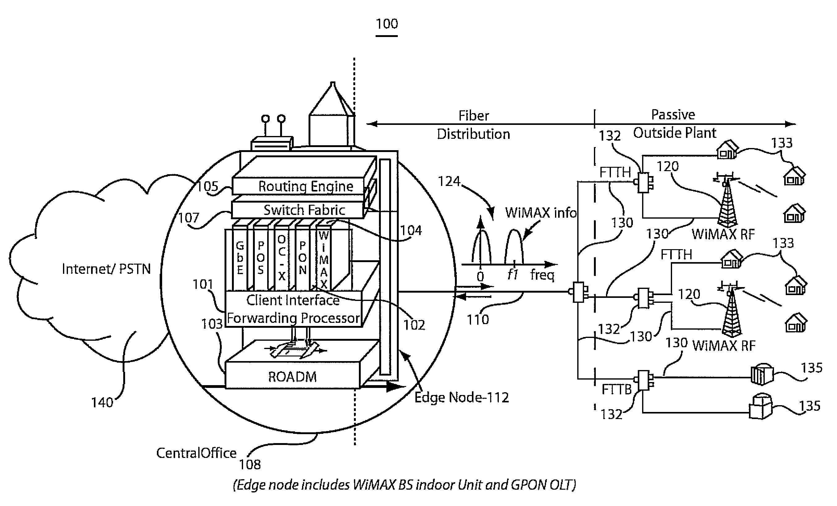
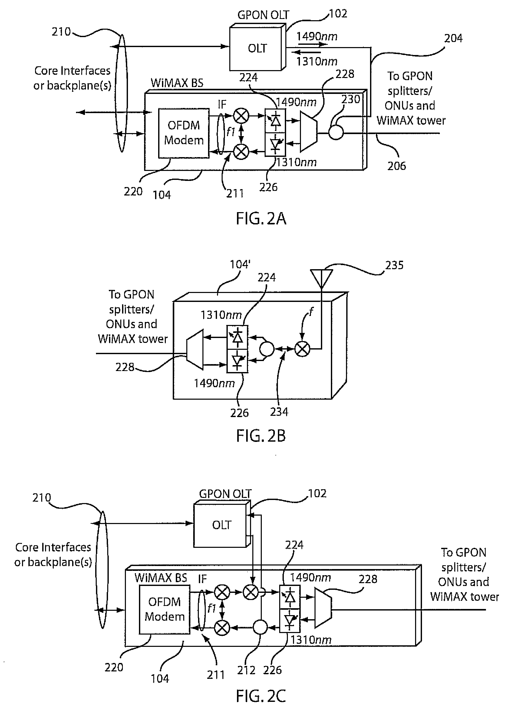
[0030]Embodiments in accordance with the present principles provide a wireless over passive optical network (PON) solution designed to maximize the utilization of the existing network infrastructure or those under construction while simplifying network management. In accordance with the present principles, Worldwide Interoperability for Microwave Access (WiMAX) will be employed as an illustrative telecommunications technology aimed at providing wireless data over distances. WiMAX as the wireless access technology and GPON (Gigabit PON) as the optical access technology are herein described for illustrative purposes and should not be construed as limiting the present invention as other technologies are also contemplated.

[0031]It should be understood that the elements shown in FIGS. may be implemented in various forms of hardware, software or combinations thereof. Preferably, these elements are implemented in a combination of hardware and software on one or more components. The compone...


PUM


Abstract

A network system and method include a wireless base station integrated at a central office of a service provider. The wireless base station is configured to provide portable and fixed services to customers. A passive optical network is coupled to the wireless base station at the central office to provide a link to extend an antenna for wireless operations of the wireless base station to a remote site such that a wireless signal from the wireless base station is transmitted in parallel with a passive fiber network signal through the link.

Description

RELATED APPLICATION INFORMATION[0001]This application claims priority to provisional application Ser. No. 60 / 825,277 filed on Sep. 12, 2006 and provisional application Ser. No. 60 / 882,024 filed on Dec. 27, 2006, both incorporated herein by reference.[0002]The present application is related to U.S. application Ser. No. (TBD), Attorney Docket Number 06062 (449-5), entitled “Wavelength Division Multiplexing Passive Optical Network Architecture to Provide Triple Play Services with Source-Free Optical Network Units”, filed (TBD) and incorporated herein by reference.BACKGROUND[0003]1. Technical Field[0004]The present invention relates to network systems and more particularly to a network where a wireless interface is extended through a dedicated optical fiber link.[0005]2. Description of the Related Art[0006]The emergence of broadband applications like internet protocol (IP) television (IPTV) stimulates the quick deployment of “fiber to the ‘x’” (FTTx, fiber to a particular type of custom...

Claims


Application Information

Patent Timeline
Patent Type & Authority Applications(United States)
IPC IPC(8): H04J14/00
CPCH04J14/021H04J14/0282H04J14/0298H04J14/025H04Q2011/0086H04W88/085H04J14/0246H04Q11/0067
Inventor HU, JUNQIANGWANG, TINGQIAN, DAYOULUO, YUANQIUSUEMURA, YOSHIHIKOSHIBUTANI, MAKOTO
Owner NEC CORP
Learn More