Developing device, image developing method, image forming apparatus, image forming method, and process cartridge

a development device and development method technology, applied in electrographic process devices, instruments, optics, etc., can solve the problems of difficult to obtain constant quality images, disadvantages of using two-component developers, and compact development devices,

Inactive Publication Date: 2008-03-13
RICOH KK
View PDF13 Cites 26 Cited by
  • Summary
  • Abstract
  • Description
  • Claims
  • Application Information

AI Technical Summary

Benefits of technology

[0031] The object of the present invention is therefore to provide an image forming apparatus, an image forming method and a process cartridge each of which allows for maintaining the conveyance amount of a toner within a certain definite range.

Problems solved by technology

The former method, i.e., the method using a two-component developer allows for obtaining a favorable image in relatively stable condition, however, it is difficult to obtain images having constant quality over a long period of time because deterioration of carrier and a variation in mixture ratio of a toner and carrier and the like easily occur.
Further, the method using a two-component developer is disadvantageous in controlling maintenance of developing devices and in making an developing device compact.
When a toner layer is thick, only the surface of the toner layer is charged and it is difficult for the entire toner layer to be charged evenly.
As a result, background smear in non-image-formed portions, toner bleed, toner scattering and the like easily occur.
However, the method disclosed in JP-B No. 2754539 specifies combinations of external additives to be used, however, the method has a difficulty in controlling a toner conveyance amount within a specific range while preventing desorption and imbedding of various external additives.
However, the methods respectively have a difficulty in controlling a toner conveyance amount within a desired range for the above-noted reasons.
Even if a toner conveyance amount is controllable, the method disclosed in JP-A No. 2004-279912 has a difficulty in ensuring a sufficient developed amount of a toner with the use of the lower limit value of the specified range of mass ratio for the negatively chargeable silica fine particle and the positively chargeable silica fine particle and is likely to cause image density defects.
The method disclosed in JP-A No. 2004-279913 has a difficulty in uniformly charging a toner with the use of the upper limit value of the specified range of mass ratio for the negatively chargeable silica fine particle and the positively chargeable silica fine particle and is likely to cause background smear in non-image formed portions, toner bleed and toner scattering.
Further, it is difficult to prevent occurrence of image nonuniformity.
In the method disclosed in JP-A No. 2002-31913, a magnesium silicate mineral used as a treatment agent has a high moisture content, and the method is likely to cause charge defects even in normal use environments as well as to cause troubles attributable to charge defects such as background smear, toner bleed, toner scattering and the like.
The methods disclosed in Japanese Patent Application Laid-Open (JP-A) Nos. 3-294864 and 4-214568 respectively have problems of causing degradation in toner flowability and increases in charged amount by the use of the silicone oil and of causing toner conveyance defects and reductions in image density in a developing device.
In the method disclosed in JP-A No. 11-95480, when a negatively chargeable toner is used, there is a problem that a reversely charged toner is likely to be generated, which easily leads to occurrence of background smear.
The method disclosed in JP-A No. 11-184239 has a problem that a leaked amount of charge is large because the electric resistance of the titanium acid fine powder is low.
Therefore, background smear, toner bleed and toner scattering easily occur.
Further, the titanium acid fine powder is prone to break away from a toner and when a contact-charge process is employed, the titanium acid fine powder causes contamination of the contact-charge members and charge defects of the used photoconductor, ending up with occurrence of image defects.
Further, the method disclosed in JP-A No. 2003-186240 has a difficulty in adjusting the additive amount of titania because titania is a material having electrically low resistance and a high dielectric constant.
When a large amount of titania is added, the leaked amount of charge is large, which causes reduction in charged amount of the entire toner.
Thus, in either case, background smear, toner bleed and toner scattering are likely to occur.
Further, when a titania having a relatively large particle diameter is used, the titania is prone to break away from the toner.
Accordingly, when a contact-charge process is employed, titania causes contamination of the contact-charge members and charge defects of the used latent electrostatic image bearing member, ending up with occurrence of image defects.
Furthermore, the method disclosed in JP-A No. 2004-264428 uses a developing device using a one-component nonmagnetic toner, the developing device is not a developing device of which such a toner is applied to a controlling member (blade).

Method used


Image

  • Developing device, image developing method, image forming apparatus, image forming method, and process cartridge
  • Developing device, image developing method, image forming apparatus, image forming method, and process cartridge

Examples


example 1

[0102] Hereinafter, the embodiment of the present invention will be further described in detail referring to specific Examples and Comparative Examples, however, the present invention is not limited to the disclosed Examples.

(Preparation of Primary Binder Resin)

[0103] As a vinyl monomer, 600 g of styrene, 110 g of butyl acrylate, 30 g of acrylic acid and as a polymerization initiator, 30 g of dicumyl peroxide were placed in a dripping funnel. In a 5-liter four-opening flask equipped with a thermometer, a stainless-steel stirrer, a falling condenser and a nitrogen inlet tube, as polyols among polyester monomers, 1,230 g of polyoxypropylene (2.2)-2,2-bis(4-hydroxyphenyl) propane, 290 g of polyoxyethylene (2.2)-2,2-bis(4-hydroxyphenyl) propane, 250 g of isododecenyl succinic anhydride, 310 g of terephthalic acid, 180 g of benzene-1,2,4-tricarboxylic anhydride, 7 g of dibutyltin oxide as an esterified catalyst and 340 g (11.0 parts by mass to 100 parts by mass of the monomer) of para...


PUM


Abstract

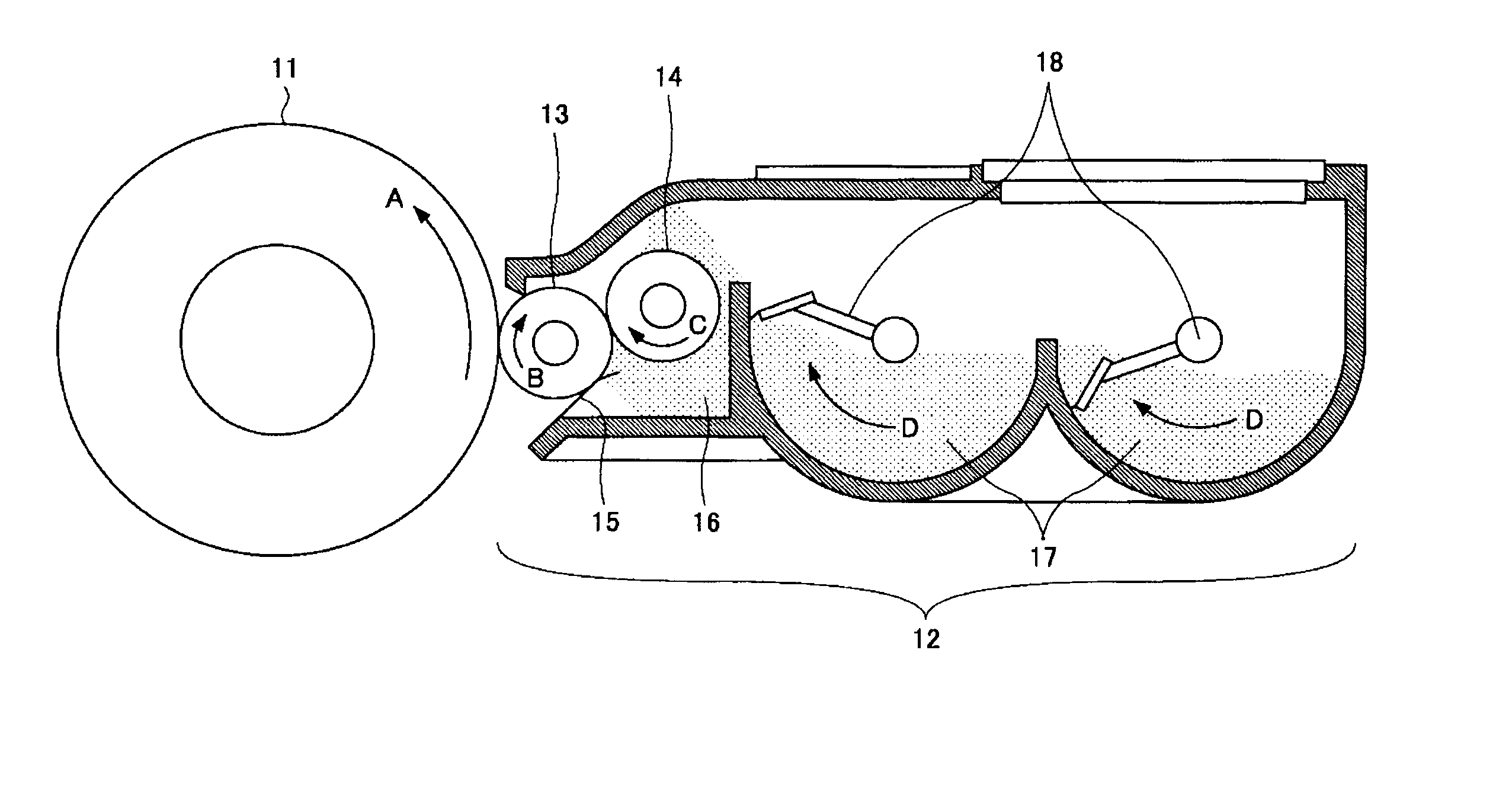
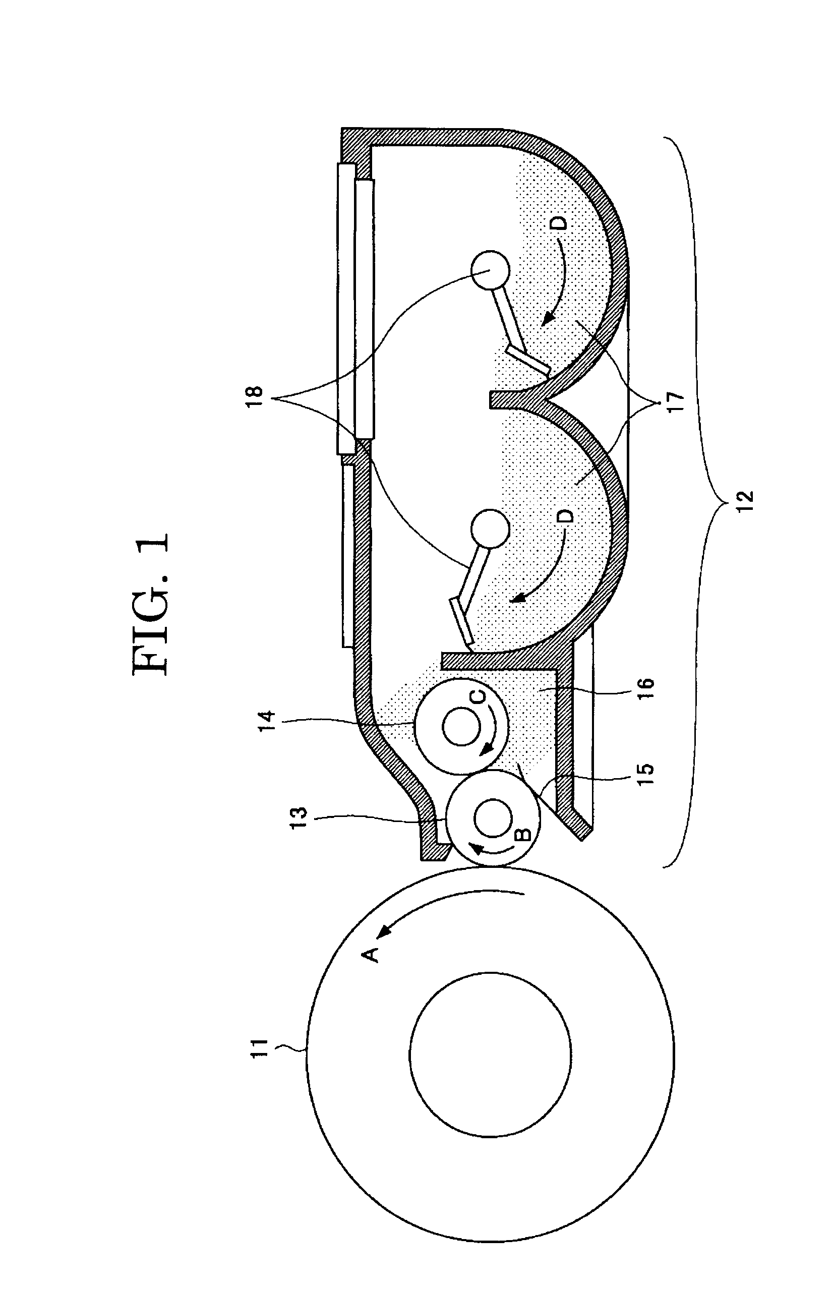
The present invention provides a developing device that allows for maintaining the conveyance amount of a toner within a certain definite range. A developing device 12 of the present invention is provided with a toner conveying unit 13 configured to convey a fist toner and a controlling member 15 configured to control the thickness of a toner layer formed with the first toner conveyed by the toner conveying unit 13, wherein a second toner provided with a charged amount per unit mass that differs from a charged amount per unit mass of the first toner is applied over the surface of the controlling member 15.

Description

BACKGROUND OF THE INVENTION [0001] 1. Field of the Invention [0002] The present invention relates to a developing device, an image developing method, an image forming apparatus, an image forming method and a process cartridge. [0003] 2. Description of the Related Art [0004] Conventionally, in electrophotography, an image has been formed by developing a latent electrostatic image formed by charging or exposing a photoconductor surface with color toners to form a toner image, transferring the toner image onto an image transfer member such as a transfer sheet and fixing the toner image formed on the transfer sheet using a heat roller or the like. [0005] Dry process developing methods employed in electrophotographic process and electrostatic recording etc. are divided into two streams, i.e., a method using a two-component developer containing a toner and a carrier and a method using a one-component developer containing no carrier. The former method, i.e., the method using a two-componen...

Claims


Application Information

Patent Timeline
Patent Type & Authority Applications(United States)
IPC IPC(8): G03G13/04G03G15/08
CPCG03G15/0812
Inventor MURAKAMI, HIROYUKIINOUE, MASAHIDEHAGI, MASAYUKIKADOTA, TAKUYAMIKURIYA, YOSHIHIROKUROSE, KATSUNORIYASUNAGA, HIDEAKIKATO, HIROAKIISHIKAWA, YOSHIMICHIFUWA, KAZUOKI
Owner RICOH KK
Why Eureka
Try Eureka