
Plasma processing apparatus, method for detecting abnormality of plasma processing apparatus and plasma processing method

Inactive Publication Date: 2008-03-20
PANASONIC CORP
View PDF4 Cites 226 Cited by
  • Summary
  • Abstract
  • Description
  • Claims
  • Application Information

AI Technical Summary

Benefits of technology

[0014]In view of the above, it is an objective of the present invention to provide a plasma processing apparatus that can reliably detect very small gas flow fluctuation and pressure fluctuation by less expensive methods, independently of process conditions, a method for detecting its abnormalities and a plasma processing method.
[0024]The present invention enables reliably detecting a very small fluctuation of about 0.1 Pa in the process chamber that could not be detected before. A fluctuation of about 1 sccm in supply amount of a process gas introduced into the process chamber can also be detected as a very small pressure fluctuation in the process chamber. Namely, processing deficiencies caused by a zero point shift of the pressure measurement unit for measuring the pressure in the process chamber, processing deficiencies caused by abnormal discharge, processing deficiency caused by fluctuation of the supplied amount of a process gas, processing deficiency caused by leakage of He gas as the heating medium of rear side of wafer, etc. can be reliably detected during the initial period of abnormality occurrence. As a result, the present invention enables reliably detecting abnormality occurrence and preventing the occurrence of continuous and considerable processing deficiencies.

Problems solved by technology

However, in the method for detecting abnormality of a plasma processing apparatus disclosed in the above Japanese Laid-Open Patent Application H11-193464, a significant change such as the deposition of reaction products on the exhaust side can be detected, but a very small gas flow fluctuation or pressure fluctuation cannot be detected.
For example, when very small fluctuations occur due to abnormal discharge and the opening of pressure control valve fluctuates, whether the fluctuation is a normal fluctuation or a fluctuation due to abnormalities cannot differentiate.
In the technique for providing detectors, such as flowmeter, for detecting abnormality, many detectors must be provided in accordance with abnormalities to be detected, therefore a practically difficult case is assumed from the standpoint of the layout and cost of the apparatus.

Method used


Image

  • Plasma processing apparatus, method for detecting abnormality of plasma processing apparatus and plasma processing method
  • Plasma processing apparatus, method for detecting abnormality of plasma processing apparatus and plasma processing method
  • Plasma processing apparatus, method for detecting abnormality of plasma processing apparatus and plasma processing method

Examples


first embodiment

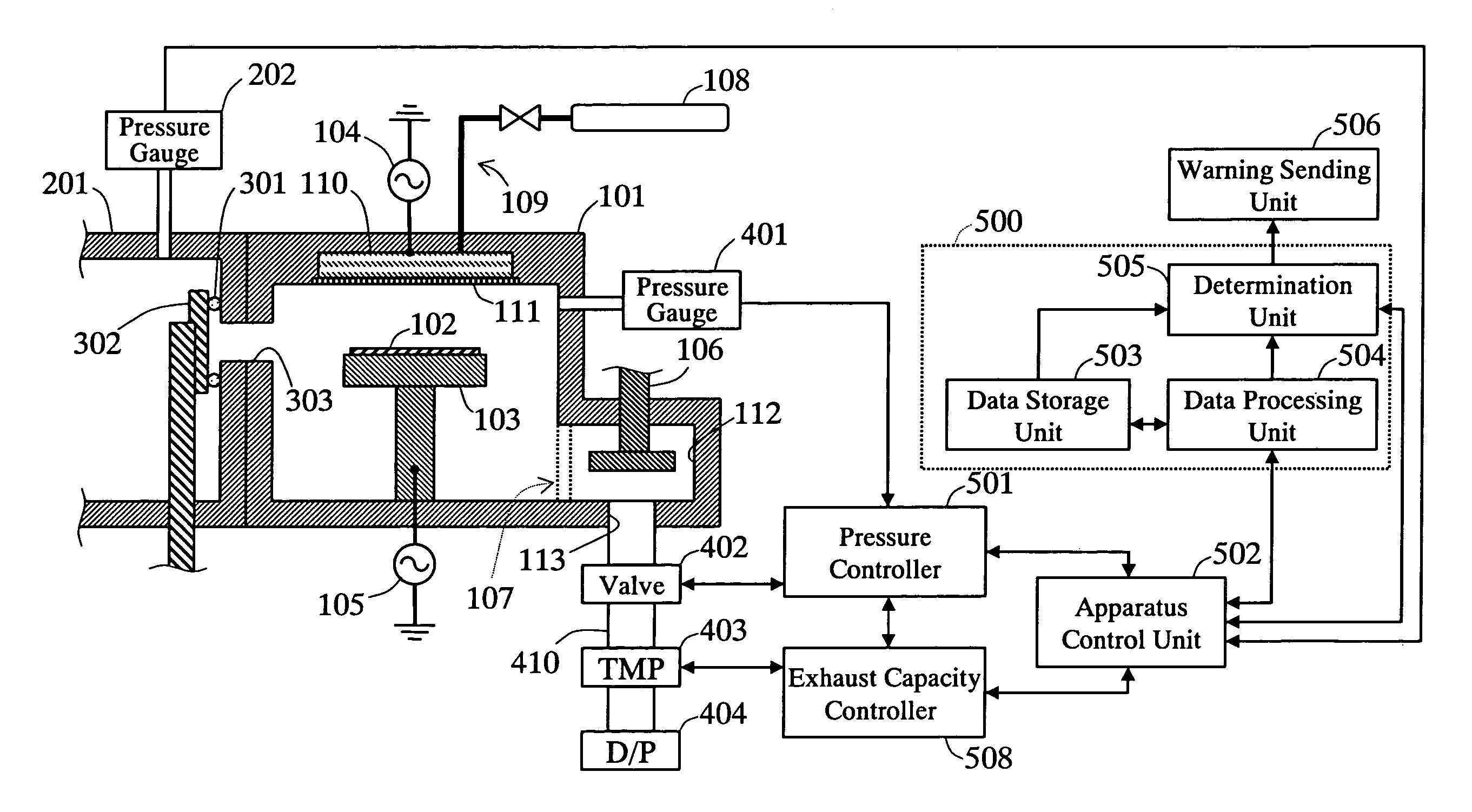
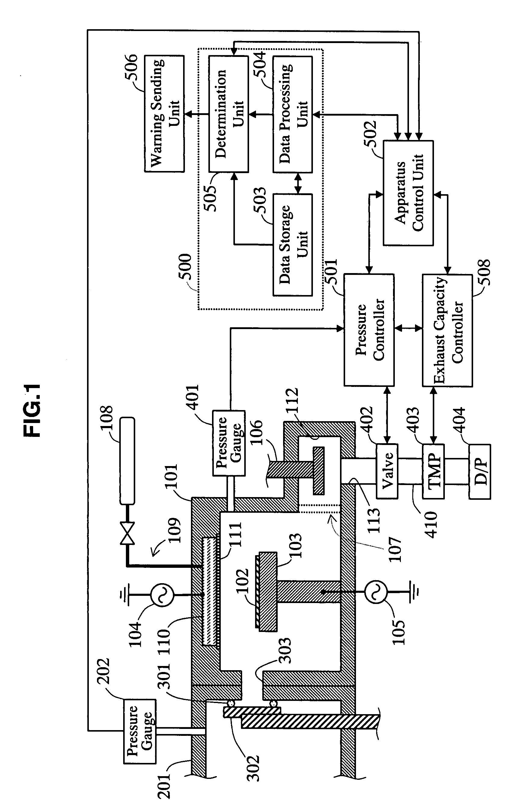
[0036]The first embodiment relating to the present invention is described hereafter with reference to the drawings. FIG. 1 is a sectional view of a plasma processing apparatus in the first embodiment of the present invention.

[0037]As shown in FIG. 1, the plasma processing apparatus of this embodiment comprises a process chamber 101 for performing a plasma processing and a wafer transport chamber 201 communicated by a wafer transport path 303. A gate valve 302 for isolating a plasma atmosphere from the process chamber 101 is provided in the wafer transport path 303 with openable / closeable.

[0038]The wafer transport chamber 201 has a conveyance mechanism (non-illustrated) for conveying a wafer 102 into and out of the process chamber 101. The gate valve 302 is placed on the wafer transport chamber 201 side, and a gate valve O-ring 301 is fixed to a surface in touch with the inner surface of the wafer transport chamber 201. A pressure measuring unit 202 for measuring the pressure in the ...

second embodiment

[0085]In the first embodiment, the exhaust capacity is reduced by changing the revolution of turbo molecular pump 403. However, the exhaust capacity can also be reduced by other techniques. FIG. 7 is a sectional view showing the construction of a plasma processing apparatus in the second embodiment relating to the present invention.

[0086]As shown in FIG. 7, the plasma processing apparatus of this embodiment is different from the plasma processing apparatus of the first embodiment in that it comprises an exhaust capacity control valve 405 between the pressure control valve 402 and the turbo molecular pump 403 as a means for reducing the exhaust capacity. Moreover, the plasma processing apparatus of this embodiment comprises an exhaust capacity controller 509 for controlling the opening of the exhaust capacity control valve 405 in place of the exhaust capacity controller 508 of the first embodiment. Other constructions are same as those of the plasma processing apparatus of the first ...

third embodiment

[0089]The exhaust capacity can also be reduced by a construction different from the first and the second embodiments. FIG. 8 is a sectional view showing the construction of a plasma processing apparatus in the third embodiment relating to the present invention.

[0090]As shown in FIG. 8, the plasma processing apparatus of this embodiment is different from the plasma processing apparatus of the first embodiment in that it comprises a gas supply port 406 between the pressure control valve 402 and the turbo molecular pump 403 as a means for reducing the exhaust capacity. A gas supply source 408 is connected to the gas supply port 406 via a gas flow controller (mass flow controller) 407. Moreover, the plasma processing apparatus of this embodiment comprises an exhaust capacity controller 510 for regulating the gas flow rate of the gas flow controller 407 in place of the exhaust capacity controller 508 of the first embodiment. Other constructions are same as the plasma processing apparatus...


PUM

PropertyMeasurementUnit
Pressureaaaaaaaaaa
Flow rateaaaaaaaaaa

Abstract

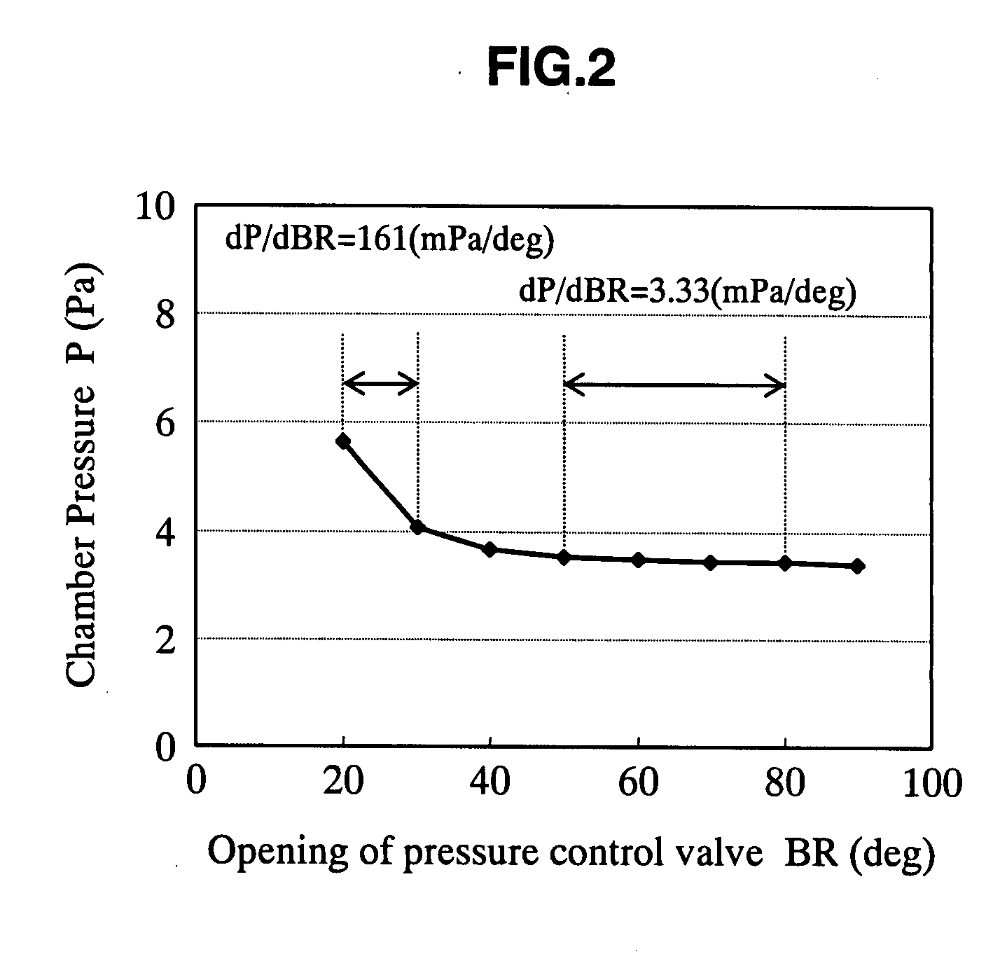
The plasma processing apparatus relating to the present invention is provided with a process chamber, a pressure measuring unit for measuring the pressure inside of the process chamber and a pump for exhausting a gas in the process chamber. A pressure control valve for maintaining the pressure inside of the process chamber to a predetermined pressure by regulating an opening based on a measured value of the pressure measuring unit is provided between the pump and the process chamber. An exhaust capacity controller sets up the exhaust capacity in a state that the variation of the opening of the pressure control valve in response to the pressure fluctuation inside of the process chamber is large. A computing unit detects very small pressure fluctuation based on the variation of the opening of the pressure control valve. In results, enabling reliable detection of a very small gas flow fluctuation and pressure fluctuation by a less expensive method independent of process conditions.

Description

CROSS-REFERENCE TO RELATED APPLICATION[0001]The present application claims the benefit of patent application number 2006-250990, filed in Japan on Sep. 15, 2006, the subject matter of which is incorporated herein by reference.BACKGROUND OF THE INVENTION[0002]1. Field of the Invention[0003]The present invention relates to a plasma processing apparatus for performing plasma processing of an object arranged in a process chamber, a method for detecting abnormality of the apparatus and a plasma processing method.[0004]2. Description of the Related Art[0005]Recently, the specification of processing conditions has tended to become technologically stricter, with high-integration, high functionalization and acceleration of operating speed of semiconductor integrated circuit devices (hereafter referred to as semiconductor devices). The manufacturing cost of semiconductor devices also has tended to rise in terms of management and reducing processing deficiencies has been desired in terms of co...

Claims


Application Information

Patent Timeline
IPC IPC(8): B05D1/00B05C5/00G01N7/00
CPCC23C16/52H01J37/32449H01L21/67288H01L21/67069H01L21/67253H01J37/32935
Inventor ONISHI, KATSUHIKOIMAMURA, HIROKI
Owner PANASONIC CORP
Learn More