
Method and apparatus for flux coating of heat exchanger tube

a technology of heat exchanger tubes and flux coatings, which is applied in the direction of tubular elements, pretreated surfaces, coatings, etc., can solve the problems of corroding parts in the heating furnace, oxidizing the surface of aluminum, and conventional flux coating methods that consume a large amount of flux, so as to shorten the flux coating time and reduce the amount of coating flux powder.

Inactive Publication Date: 2008-03-20
LG CABLE LTD (KR)
View PDF3 Cites 6 Cited by
  • Summary
  • Abstract
  • Description
  • Claims
  • Application Information

AI Technical Summary

Benefits of technology

[0014] The present invention is designed to solve the problems of the prior art, and therefore the present invention is directed to shortening a flux coating time onto a heat exchanger tube, reducing a coating amount of flux powder, and ensuring uniform flux coating such that the heat exchanger tube may be joined without an error during the joining process.

Problems solved by technology

If such a mixture solution is not used, an oxide film formed on the aluminum is cracked due to the difference of thermal expansion coefficients of the aluminum and the oxide film, so the aluminum surface is oxidized.
However, the conventional flux coating method consumes a large amount of flux due to moisture since the flux is sprayed in a liquid state mixed with water.
In addition, a large amount of flux coated on the heat exchanger tube generates moisture while being heated in a heating furnace, thereby corroding parts in the heating furnace.
Also, the flux may be coated excessively in regions other than the joining area and then penetrated into a coupling surface of a jig and the heat exchanger in a melt state.
In a severe case, the heat exchanger should be wasted since the heat exchanger is adhered to the jig.
However, the coating method of the first document needs a separate drying process since it uses a liquid paste.
In addition, due to bad adhesive force to a part, the coating may be separated to deteriorate junction when an additional handling process is conducted.
Here, in case the coating is irregular, erosion may occur in a region where the coating is excessive, and irregular junction occurs in a region where the coating is deficient.
In addition, the coating method of the second document has problems that the flux is stuck to an extruding roller during the extruding process, so the extruding itself becomes difficult.
Moreover, the coating methods of the above documents are all undesirable since dust occurring in the flux coating process deteriorates working environment, productivity according to the process time is not efficient, and thickness and amount of coated flux are not easily controlled.

Method used


Image

  • Method and apparatus for flux coating of heat exchanger tube
  • Method and apparatus for flux coating of heat exchanger tube
  • Method and apparatus for flux coating of heat exchanger tube

Examples


Embodiment Construction

[0038] Hereinafter, preferred embodiments of the present invention will be described in detail with reference to the accompanying drawings. Prior to the description, it should be understood that the terms used in the specification and the appended claims should not be construed as limited to general and dictionary meanings, but interpreted based on the meanings and concepts corresponding to technical aspects of the present invention on the basis of the principle that the inventor is allowed to define terms appropriately for the best explanation. Therefore, the description proposed herein is just a preferable example for the purpose of illustrations only, not intended to limit the scope of the invention, so it should be understood that other equivalents and modifications could be made thereto without departing from the spirit and scope of the invention.

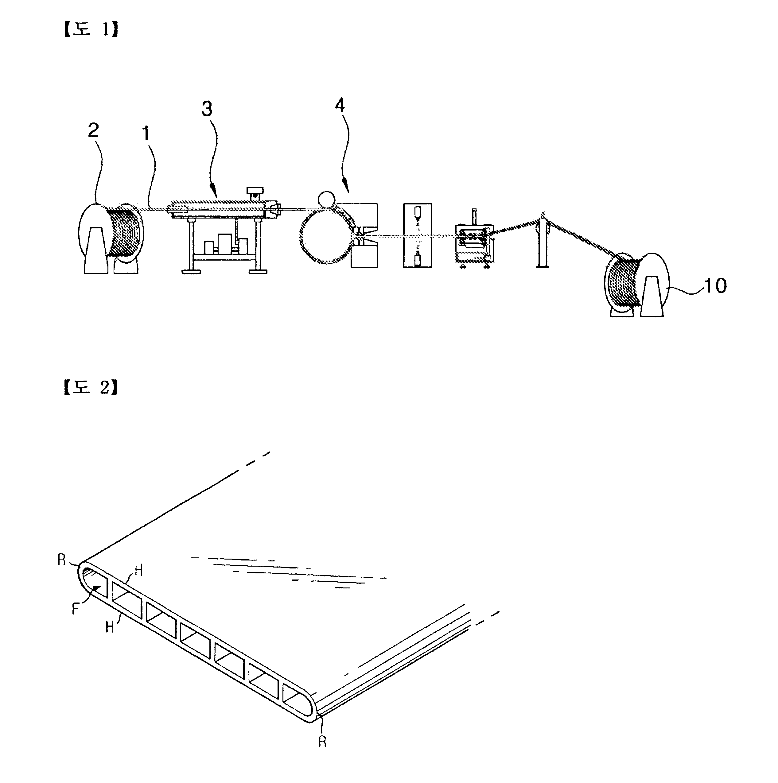
[0039] A heat exchanger tube according to an embodiment of the present invention is a rolled board having a plurality of flow passag...


PUM

PropertyMeasurementUnit
thicknessaaaaaaaaaa
timeaaaaaaaaaa
thicknessaaaaaaaaaa

Abstract

For flux coating of a heat exchanger tube made of aluminum, firstly, the heat exchanger tube is dipped in a storage tank containing a mixture of binder and solvent to coat the mixture on a surface of the heat exchanger tube, thereby forming a first coating layer on the surface of the heat exchanger tube. Then, flux powder is sprayed to the surface of the heat exchanger tube on which the first coating layer is formed, thereby forming a second coating layer. After that, a thickness of the heat exchanger tube on which the second coating layer is formed is controlled. Then, the thickness-controlled heat exchanger tube is heated to 150° C. or below so as to remove the solvent from the second coating layer.

Description

BACKGROUND OF THE INVENTION [0001] 1. Field of the Invention [0002] The present invention relates to method and apparatus for flux coating of a heat exchanger tube, and more particularly to method and apparatus for allowing uniform flux coating on a heat exchanger tube used for making a heat exchanger of a vehicle. [0003] 2. Description of the Related Art [0004] A heat exchanger tube is a part used in a heat exchanger of a vehicle, and the heat exchanger tube is made of aluminum material in consideration of lightweight, high sensitivity, and thermal conduction. This heat exchanger tube is mounted to a heat exchanger of a vehicle such as a car to enable heat exchange at high efficiency, accordingly working for fuel reduction of the vehicle. [0005] Commonly, a heat exchanger tube used for a heat exchanger of a vehicle is called a PFC (Parallel Flow Condenser) tube, which is made by extruding an aluminum wire into a tubular shape. The process of making a conventional heat exchanger tub...

Claims


Application Information

Patent Timeline
Patent Type & Authority Applications(United States)
IPC IPC(8): B05D1/36B05C19/04B05C3/02
CPCB05D1/12B05D1/18B05D3/0254B05D7/14F28F21/089B05D2202/25B05D2254/00F28F1/022F28F21/084B05D7/54B05D1/16B05D1/02
Inventor LEE, SANG-HEONYOON, JONG-SEOSHIN, YOUN-HAKLEE, BYOUNG-KWANG
Owner LG CABLE LTD (KR)
Learn More