Low friction sliding mechanism

a sliding mechanism and low friction technology, applied in the field of low friction sliding mechanism, can solve the problems of limited friction lowering effect, difficulty in obtaining a further friction reduction effect, and limited added amount, and achieve the effect of low friction sliding, effective overcome drawbacks, and low friction

Inactive Publication Date: 2008-03-20
NISSAN MOTOR CO LTD
View PDF5 Cites 22 Cited by
  • Summary
  • Abstract
  • Description
  • Claims
  • Application Information

AI Technical Summary

Benefits of technology

[0007]It is, therefore, an object of the present invention to provide an improved low friction sliding mechanism which can effectively overcome drawbacks encountered in conventional low friction sliding mechanisms.
[0008]Another object of the present invention is to provide an improved low friction sliding mechanism in which a friction coefficient of a sliding member can be extremely lowered.

Problems solved by technology

In this regard, polytetrafluoroethylene hampers a lipophilicity of the resinous composition, and therefore its added amount is limited from the viewpoint of ensuring a wettability.
As a result, there is a limit in friction lowering effect, encountering a difficulty of obtaining a further friction reduction effect.
Thus, this technique is still insufficient from the viewpoint of the friction reduction.

Method used


Image

  • Low friction sliding mechanism
  • Low friction sliding mechanism

Examples


example 1

Preparation of Resinous Material Precursor 1

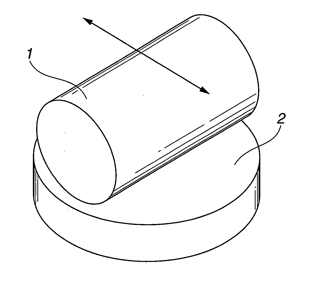
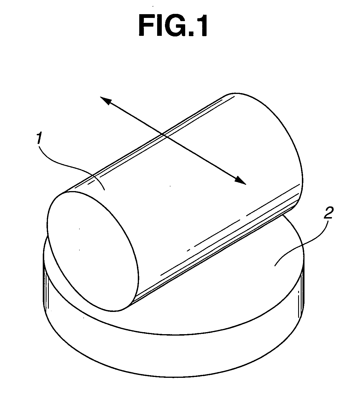
[0049]Powdery diamond particles (having a primary particle size ranging from 4 to 5 nm) obtained by a detonation process was added into N-methyl-2-pyrrolidone (NMP) and then stirred in a bead mill for 30 minutes to form a mixture. Thereafter, polyamideimide resin (having a number average molecular weight of 6000) synthesized by an isocyanate process was added to the mixture so as to prepare a resinous material (resin composition) precursor 1 containing 1% of the diamond particle based on the polyamideimide resin.

[0050]

[0051]Defatting with alcohol was made on a disc (having a diameter of 24 mm, a thickness of 7.9 mm, and a surface roughness Ra of 0.1 μm) formed of a material A6061 (according to JIS) subjected to a so-called T6 treatment (a solution heat treatment plus an age hardening treatment) and serving as a substrate. Thereafter, the above-mentioned resinous material precursor 1 was spray-coated at the surface of the disc in such a man...

example 3

[0053]The procedure of Example 1 was repeated with the exception that the resinous material precursor 1 was prepared to contain 0.1% of diamond particle based on the polyamindeimide resin, thus obtaining a sliding member to be used in a low friction sliding mechanism of this Example.

example 4

[0054]The procedure of Example 1 was repeated with the exception that the resinous material precursor 1 was prepared to contain 0.05% of diamond particle based on the polyamindeimide resin, thus obtaining a sliding member to be used in a low friction sliding mechanism of this Example.


PUM

PropertyMeasurementUnit
particle sizeaaaaaaaaaa
thicknessaaaaaaaaaa

Abstract

A low friction sliding mechanism employed in an internal combustion engine of an automotive vehicle. The low friction sliding mechanism includes first and second sliding members which are in slidable contact with each other. At least one of the first and second sliding members has a sliding surface portion whose at least a part is formed of a resinous material containing hydrophilic fine particle. Additionally, a lubricant exists between the first and second sliding members and includes a friction modifier containing at least one of organic oxygen-containing compound and aliphatic amine-based compound.

Description

BACKGROUND OF THE INVENTION[0001]This invention relates to improvements in a low friction sliding mechanism, and more particularly to the low friction sliding mechanism which can reduce a frictional resistance at a sliding section of an internal combustion engine of an automotive vehicle or the like thereby improving a fuel saving performance.[0002]Nowadays, an internal combustion engine is being strongly required to be increased in engine speed, to be increased in compression ratio and to be lightened in weight and to be improved in fuel consumption, as compared with in the past. This is assumed to be achieved by lowering friction at sliding sections of the engine.[0003]As a measure to achieve lowering friction and improving abrasion resistance and anti-seizure characteristics at the sliding sections in the engine, hitherto it has been employed to coat a substrate with a lubricating coating which is prepared by blending solid lubricants such as molybdenum disulfide, graphite, polyt...

Claims


Application Information

Patent Timeline
Patent Type & Authority Applications(United States)
IPC IPC(8): F16C33/02
CPCC10M169/04F16C33/201C10M2201/041C10M2201/061C10M2201/066C10M2201/105C10M2207/04C10M2207/28C10M2207/289C10M2209/1003C10M2213/062C10M2215/08C10M2217/0403C10M2217/0443C10M2221/0405C10N2210/04C10N2210/06C10N2220/082C10N2230/06C10N2240/10C10N2250/141C10M171/06C10N2010/08C10N2010/12C10N2020/06C10N2030/06C10N2040/25C10N2050/025
Inventor KAMADA, SEIJIUENO, TAKAFUMIHASHIMOTO, TOMIHITO
Owner NISSAN MOTOR CO LTD
Why Eureka
Try Eureka