Highly porous mullite particulate filter substrate

a technology of mullite and filter substrate, applied in the field of filters, can solve the problems of mechanical strength, undesirable effects of known filters, and contribute to (typically quick) a rise in backpressur

Inactive Publication Date: 2008-03-27
GE02 TECH INC
View PDF99 Cites 52 Cited by
  • Summary
  • Abstract
  • Description
  • Claims
  • Application Information

AI Technical Summary

Problems solved by technology

However, known filters have been found to have undesirable effects related to mechanical strength, filter backpressure (becoming especially as the filter becomes loaded with particulates), regeneration efficiency and soot trapping & ash storage efficiencies.
However, in this process, trapped soot rapidly cakes on the surface of the channel wall, thus progressively blocking gas flow paths through the porous walls and contributing to (typically quick) a rise in backpressure.
Also, since the gases are being forced though the walls, even newly constructed or freshly regenerated wall-flow filters may be characterized by unacceptably high backpressures.
In general, DPF designs to date suffer from such cake filtration effects arising from soot build-up on the wall surfaces.
As soot collects on top of the surface of the porous wall, the effective diameter of the channel is reduced, leading to a sharp rise in backpressure.
Although regeneration is an important aspect of DPF design and use, the threat of an uncontrolled regeneration limits the practicability of automated regeneration processes.
For example, an uncontrolled regeneration may result when, during normal regeneration or even during normal operation, the natural heat dissipation processes are interrupted.
However, if the car were to suddenly stop, such as due to stop-and-go traffic, the engine speed would dramatically drop, and along with it the flow of exhaust gas through the DPF.
Since exhaust gas flow is at least partially responsible for moving excess heat out of the DPF, such an event may trigger the temperature of the DPF to rise dramatically.
In the presence of the very high temperatures observed in uncontrolled soot regenerations, some refractory ceramic materials exhibit undesirable reactions such as phase transitions or the formation of phases/eutectics in the presence of impurities.
The reactions may cause a decrease in strength, melting point, or generate undesirable byproducts, resulting in physical weakening or chemical degradation of the DPF.
In some cases, such as reactions in the DPF may also lead to sintering of the c

Method used


Image

  • Highly porous mullite particulate filter substrate
  • Highly porous mullite particulate filter substrate
  • Highly porous mullite particulate filter substrate

Examples


Embodiment Construction

[0038]Detailed descriptions of examples of the invention are provided herein. It is to be understood, however, that the present invention may be exemplified in various forms. Therefore, the specific details disclosed herein are not to be interpreted as limiting, but rather as a representative basis for teaching one skilled in the art how to employ the present invention in virtually any detailed system, structure, or manner.

[0039]The drawing figures herein illustrate and refer to an exhaust system pathway that is, for the most part, specifically described as a component of an internal combustion engine exhaust system. However, it should be appreciated that the exhaust pathway may be used on other types of exhaust systems. For example, the exhaust system may be a fluidic flow system in the petrochemical, biomedical, chemical processing, painting shops, laundromat, industrial exhaust, power generation plant, water-filtration, oil-most removal, air-purification, deodorizer application, ...


PUM

PropertyMeasurementUnit
Temperatureaaaaaaaaaa
Thicknessaaaaaaaaaa

Abstract

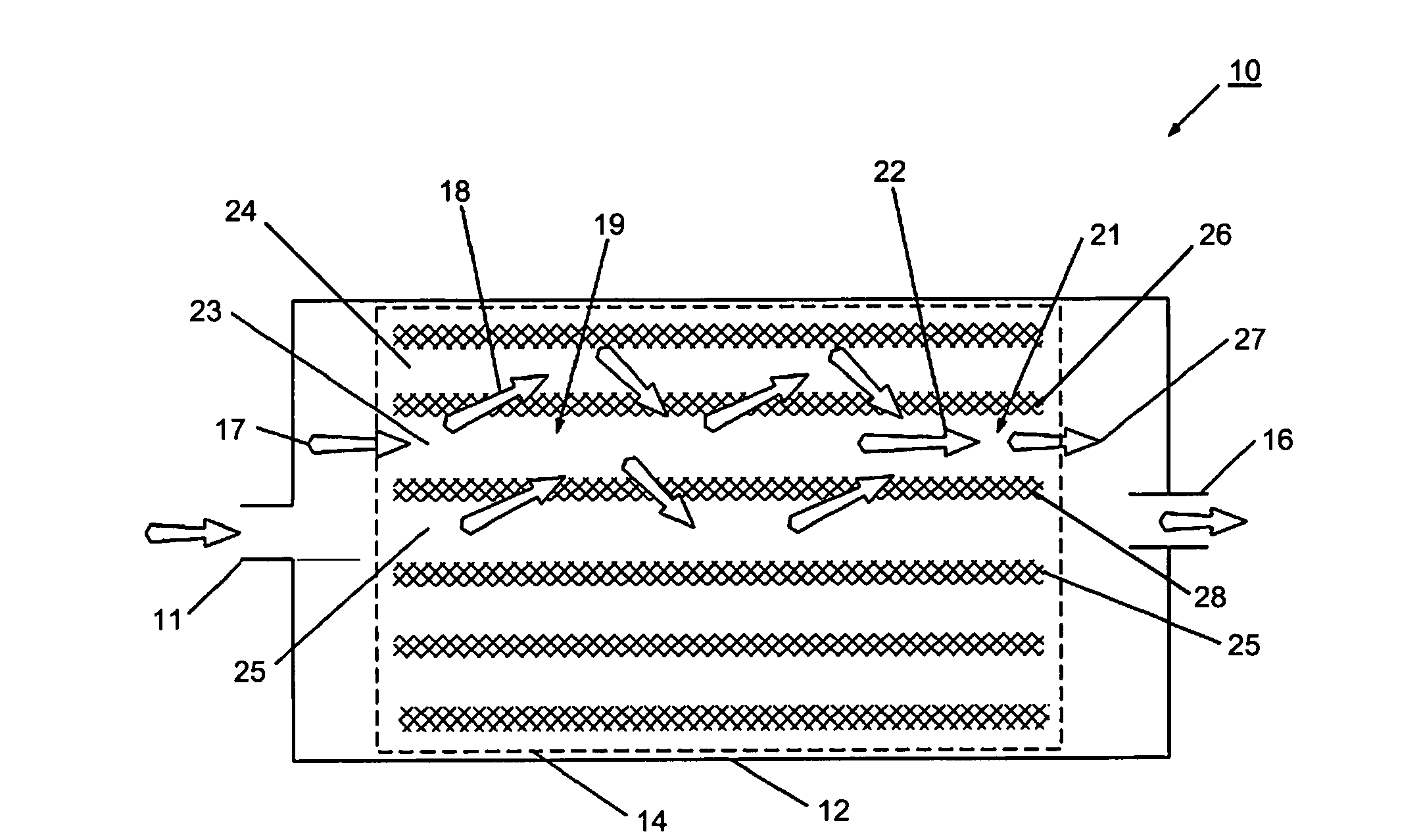
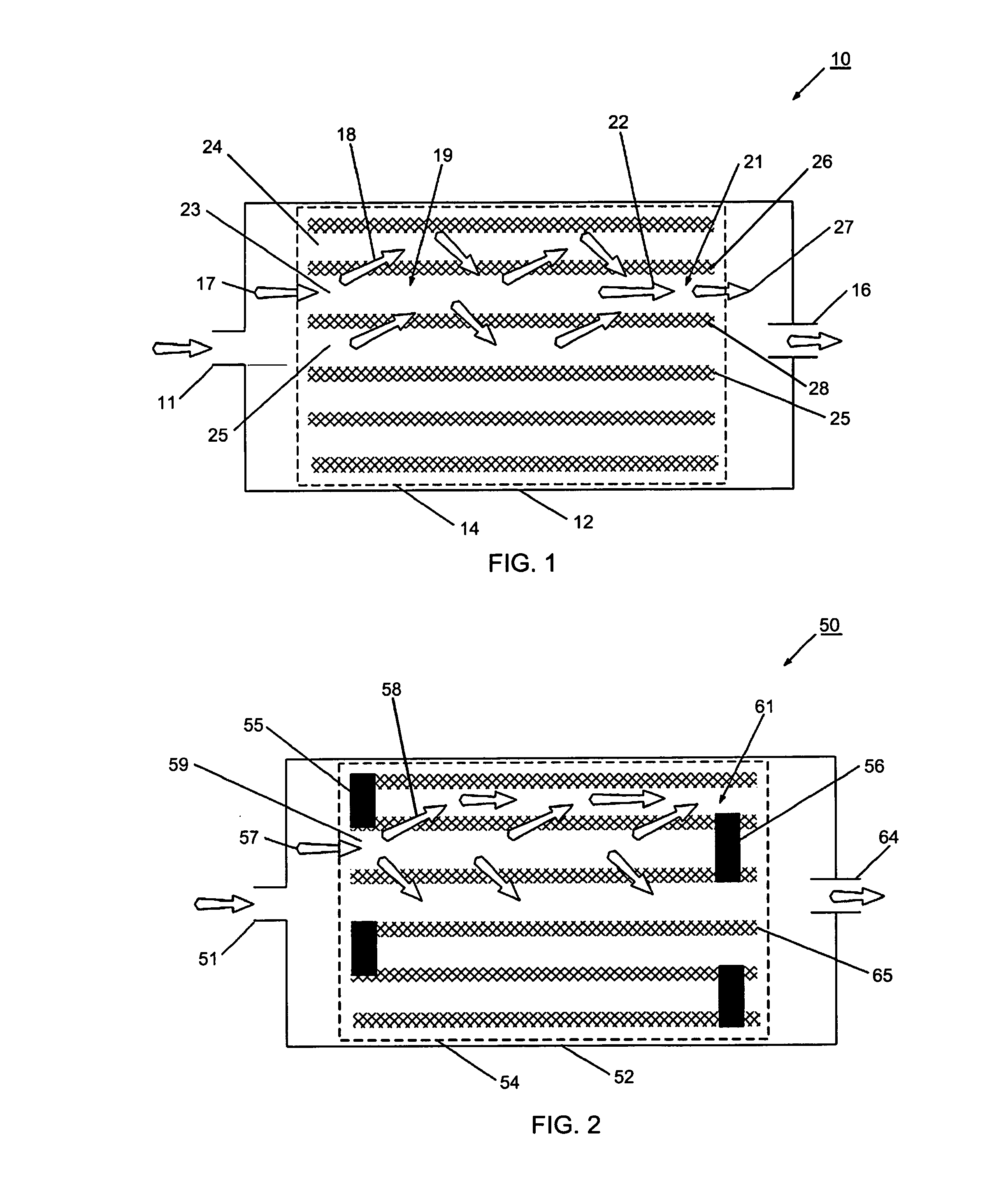
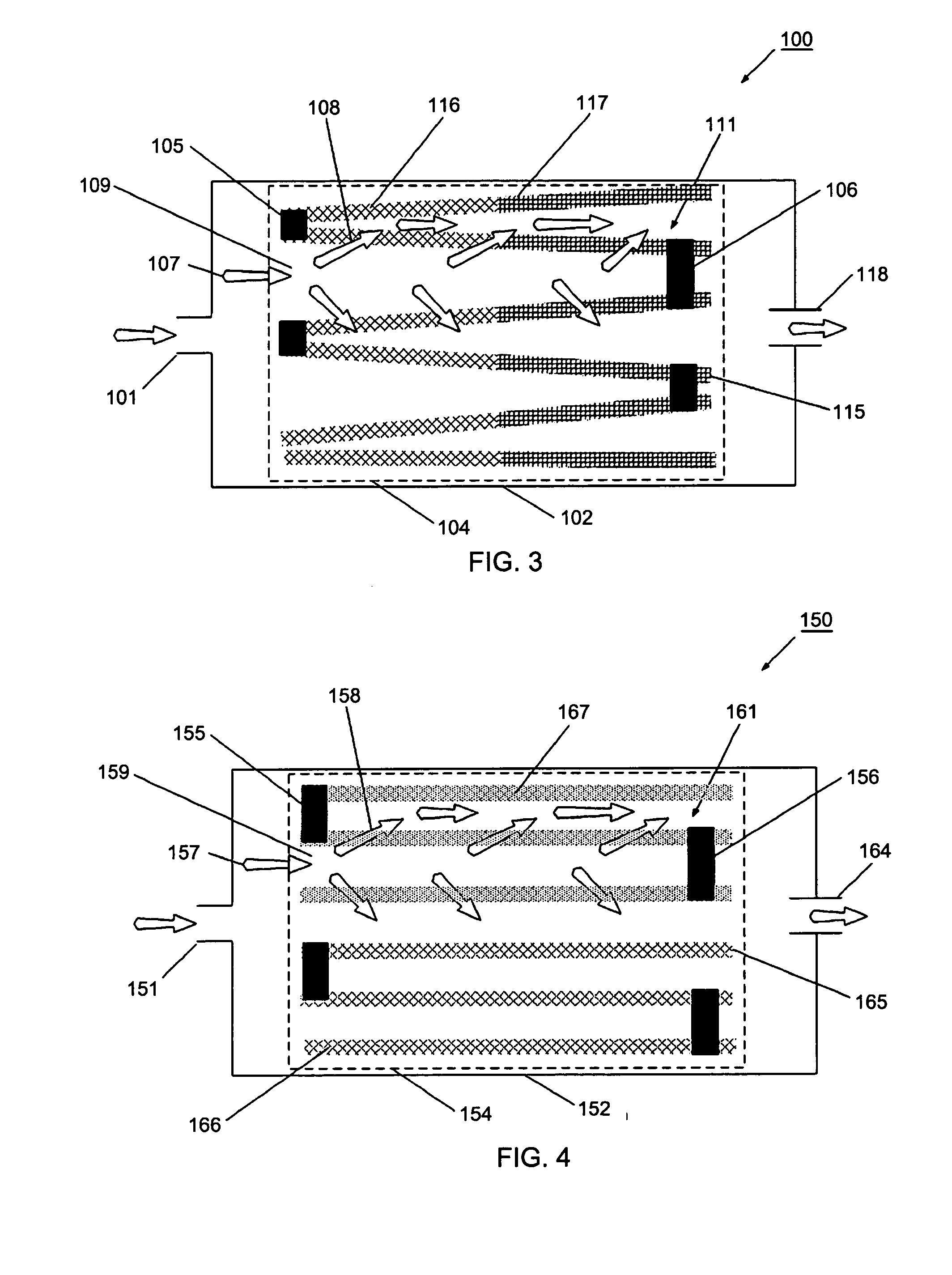
A typically monolithic particulate filter including a highly porous block made primarily of intertangled polycrystalline mullite fibers, a set of channels formed through the block, and a set of porous walls separating adjacent channels. Exhaust gas is flowed through the channels and interacts with the walls such that particulate matter carried in the exhaust gas, such as soot particles, is screened out by porous fibrous mullite walls.

Description

RELATED APPLICATIONS[0001]This application is a continuation-in-part of U.S. patent application Ser. No. 10 / 833,298, filed Apr. 28, 2004, and entitled “Nonwoven Composites and Related Products and Processes”, which is a continuation-in-part of U.S. patent application Ser. No. 10 / 281,179, filed Oct. 28, 2002, and entitled “Ceramic Exhaust Filter”, now U.S. Pat. No. 6,946,013, both of which are incorporated herein as if set forth in their entirety.BACKGROUND [0002]1. Field[0003]The present invention relates generally to a filter for removing particulate matter from an exhaust gas, and more particularly to a monolithic particulate filter.[0004]2. Description of Related Art[0005]An exhaust system for an engine is often required to reduce particulate pollutants, and therefore typically includes a particulate filter. One type of particulate filter is useful for trapping diesel exhaust particulate, and, therefore is commonly referred to as a Diesel Particulate Filter (DPF). A typical DPF i...

Claims


Application Information

Patent Timeline
IPC IPC(8): B01D53/94B01D39/20C01B33/26
CPCB01D39/2082Y02T10/22B01D46/521B01D53/944B01D53/945B01J35/04B01J35/06C03C13/00F01N3/0211F01N3/0226F01N3/027F01N3/2013F01N3/2835F01N3/2853F01N3/30F01N2330/10F01N2370/22Y02T10/26Y10S55/05Y10S55/30Y10S55/10B01D39/2086B01D53/9431C04B35/185C04B2235/5228C04B2235/5264C04B2235/5296C04B2235/6021C04B2235/77C04B38/0009C04B2111/00793C04B2111/0081Y02T10/12C04B38/0074C04B38/0096B01D53/94
Inventor ZUBERI, BILAL
Owner GE02 TECH INC
Why Eureka
Try Eureka