

Reaction cell and mass spectrometer
- Summary
- Abstract
- Description
- Claims
- Application Information
AI Technical Summary
Benefits of technology
Problems solved by technology
Method used
Image

Examples
first embodiment
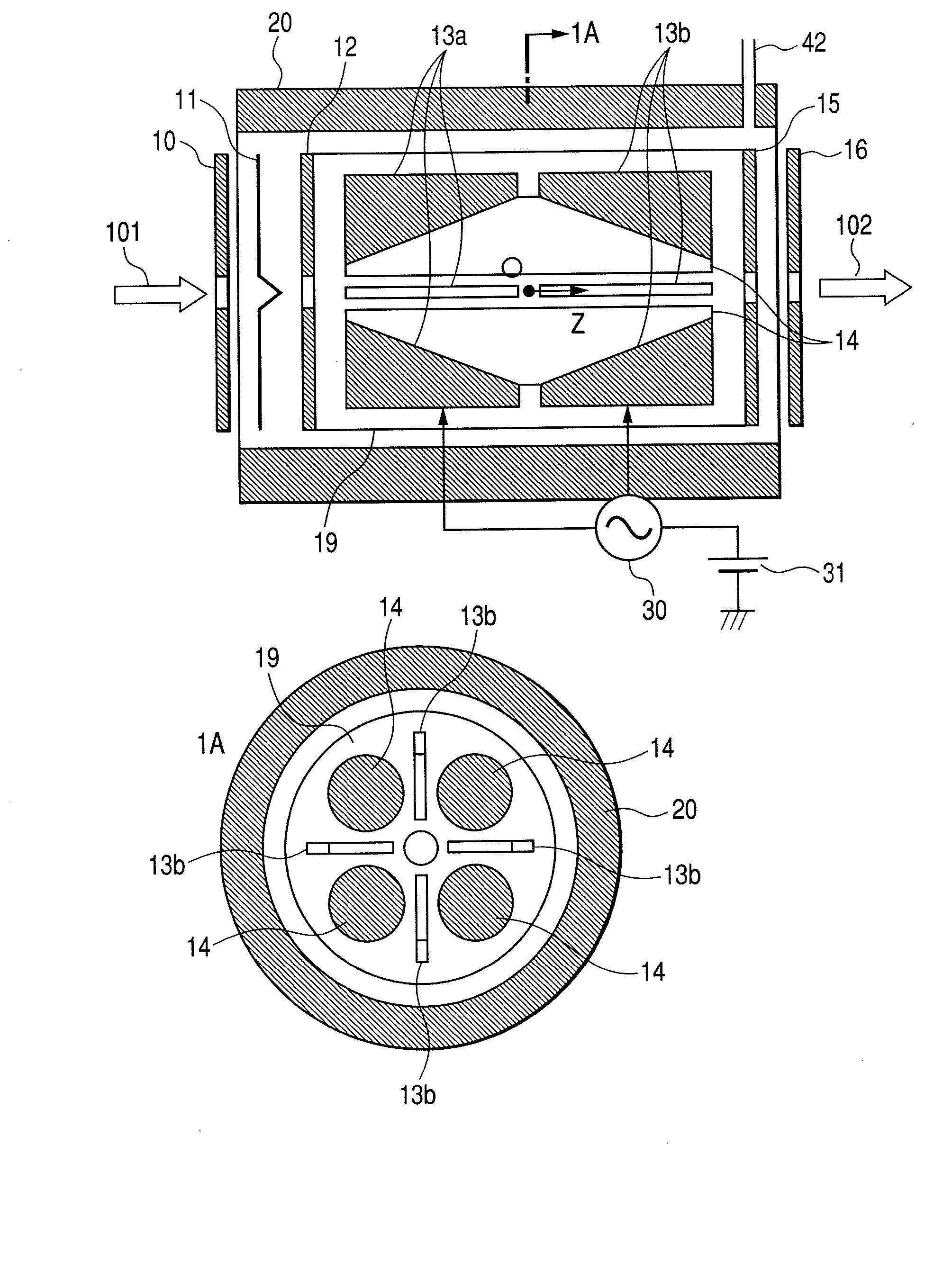
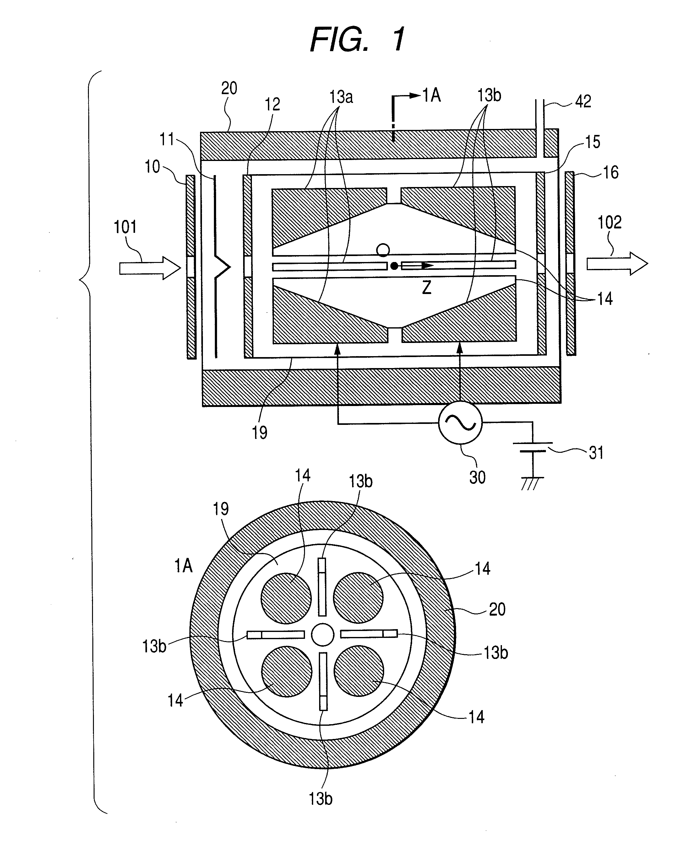
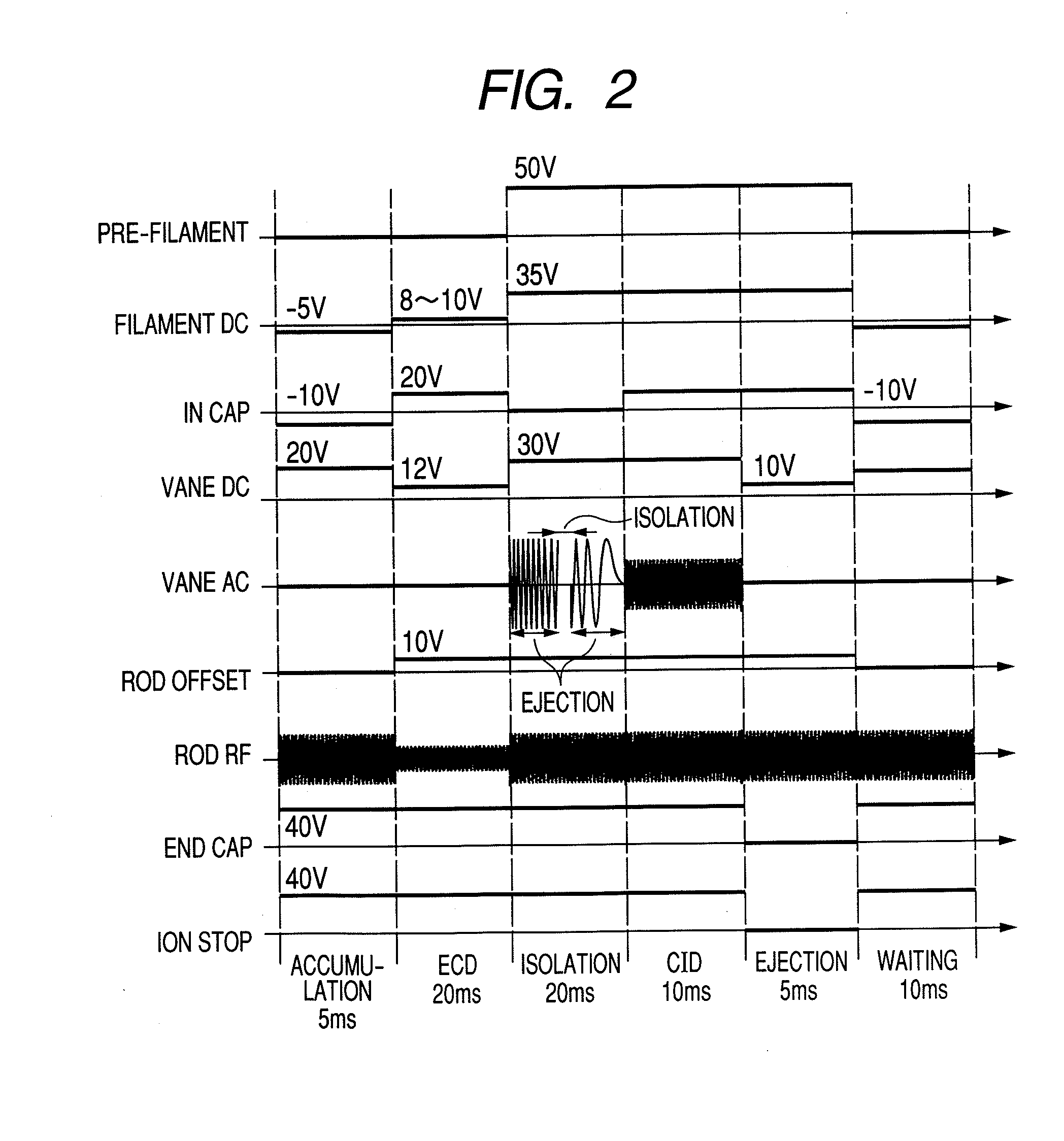
[0022]FIG. 1 contain block diagrams (cross-sectional views) illustrating an ion-trap (hereinafter, an ECD / CID trap) utilizing the present method where an ECD / CID reaction is enabled. FIG. 2 is a typical measurement sequence of an ECD / CID trap. Ions generated by various ion sources pass through the ion guide, the ion-trap, and the Q-mass filter and they are introduced into the ECD / CID trap along the direction of arrow 101. Ions passing through a pre-filament electrode 10, a filament 11, and an in-cap electrode 12 are introduced into the area surrounded by an in-cap electrode 12, rod electrode 14, an end-cap electrode 15, and electrode a fore-and-aft vane lens 13. A magnetic field from about 10 millitesla to 0.3 tesla is applied by a magnet 20 to the filament and to the area where ions are stored. An electro-magnet may be utilized as the magnet 20 in addition to a permanent magnet such as ferrite and neodymium. A material like tungsten is used for the filament 11. When a thick filamen...
second embodiment
[0029]FIG. 3 shows an embodiment when TOF is used as a mass analysis section. Ions created by an ion source 1 such as an electrospray ion source and a matrix assisted laser desorption ion source, etc. pass through an orifice 2 and are introduced into the first differential pumping chamber 3. The first differential pumping chamber 3 is exhausted by using a pump and the pressure is from about 100 to 1000 Pa. Ions introduced into the first differential pumping chamber 3 pass through the orifice 4 and are introduced into the second differential pumping chamber 5. The second differential pumping chamber 5 is exhausted by using a pump and the pressure is from about 0.1 to 3 Pa. Moreover, an ion guide 6 which applies an RF voltage to a plurality of rod electrodes is generally installed in the second differential pumping chamber 5, and ions are converged by using this guide, so that they can pass through the orifice 7 efficiently. An electrode where cylindrical electrodes are placed may be ...
third embodiment
[0030]FIG. 7 is an embodiment in the case when mass separation and detection are performed in the ECD / CID trap. The operations from the ion source 1 to the ECD / CID trap are omitted because they are similar to the second embodiment. After reaction at the ECD / DIC trap, ions having a different m / Z can be ejected, in order, by scanning the supplemental AC frequency. The ejected ions are deflected by a conversion dynode 40 and detected by using a detector 41 such as an electron multiplier, etc. Since there is a relationship shown in (expression 3) between the frequency of the supplemental AC voltage and the ejected m / Z, the m / Z can be calculated and converted to a mass spectrum. In the configuration of the third embodiment, the mass selectivity is poor compared with the configuration of the second embodiment, but there is an advantage in which the device cost can be greatly reduced. Moreover, excellent mass selectivity can be obtained within a wide range of mass by scanning the DC potent...
PUM
 Abstract
Description
Claims
Application Information