
Modulator arrangement and method for signal modulation

Inactive Publication Date: 2008-03-27
INTEL CORP
View PDF7 Cites 23 Cited by
  • Summary
  • Abstract
  • Description
  • Claims
  • Application Information

AI Technical Summary

Benefits of technology

[0013]The following presents a simplified summary in order to provide a basic understanding of one or more aspects of the invention. This summary is not an extensive overview of the invention, and is neither intended to identify key or critical elements of the invention, nor to delineate the scope thereof. Rather, the primary purpose of the summary is to present one or more concepts of the invention in a simplified form as a prelude to the more detailed description that is presented later.
[0014]In one embodiment of the invention, a modulator arrangement comprises a data input to receive amplitude data and a control input to receive power data. A power

Problems solved by technology

The modulation types which are used for modern mobile radio standards are particularly sensitive to possible distortion which is produced by various components in a transmission path.
Distortion such as this in the transmission path leads to changes in the phase and amplitude of a carrier signal.
This results in data errors in the transmitted signal.
Such a non-linearity can lead to data errors within the transmitted signal.
However, operation of a power amplifier in this way can lead to a high quiescent current being drawn, thus increasing the overall power consumption.
The use of a predistortion, however, causes a higher power consumption in a modulator arrangement or transmitting device.

Method used


Image

  • Modulator arrangement and method for signal modulation
  • Modulator arrangement and method for signal modulation
  • Modulator arrangement and method for signal modulation

Examples


Embodiment Construction

[0031]In the following description further aspects and embodiments of the present invention are summarized. In addition, reference is made to the accompanying drawings, which form a part hereof, and in which is shown by way of illustration, in which the invention may be practiced. The embodiments of the drawings present a summary in order to provide a better understanding of one or more aspects of the present invention. This summary is not an extensive overview of the invention and neither intended to limit the features or key-elements of the invention to a specific embodiment. Rather, the different elements, aspects and features disclosed in the embodiments can be combined in different ways by a person skilled in the art to achieve one or more advantages of the present invention. It is to be understood that other embodiments may be utilized and structural or logical changes may be made without departing from the scope of the present invention. The elements of the drawing are not ne...


PUM


Abstract

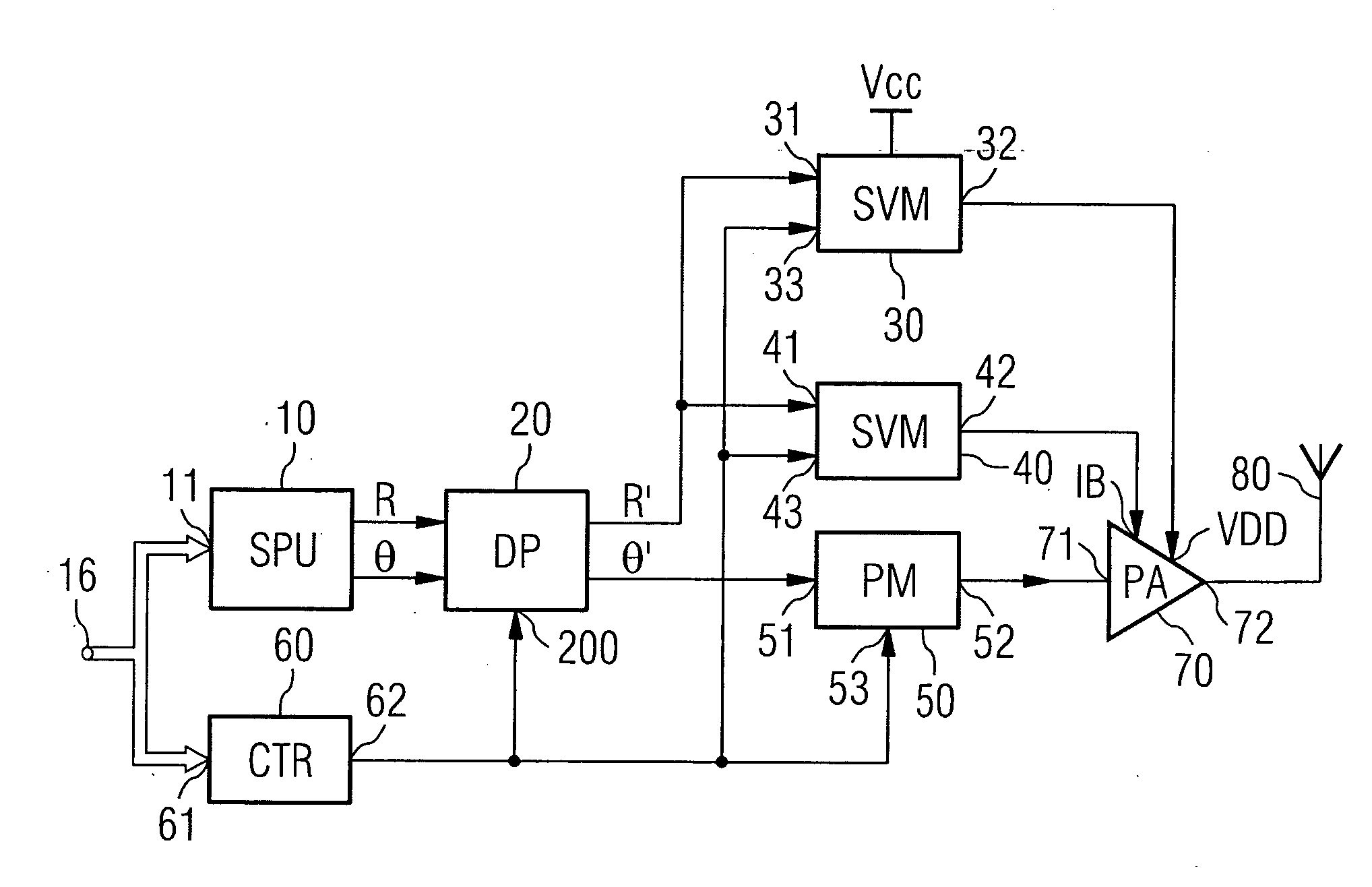
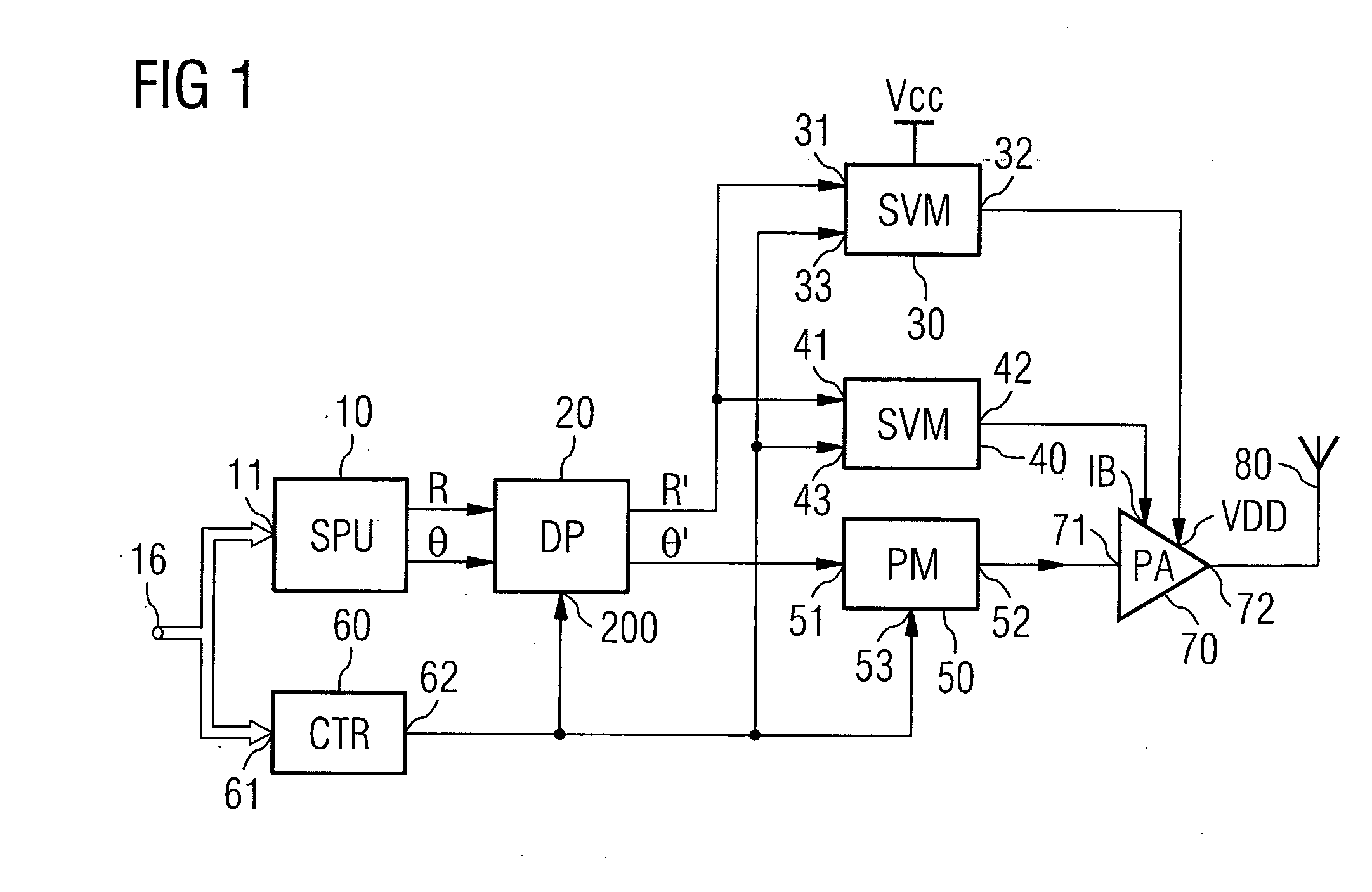
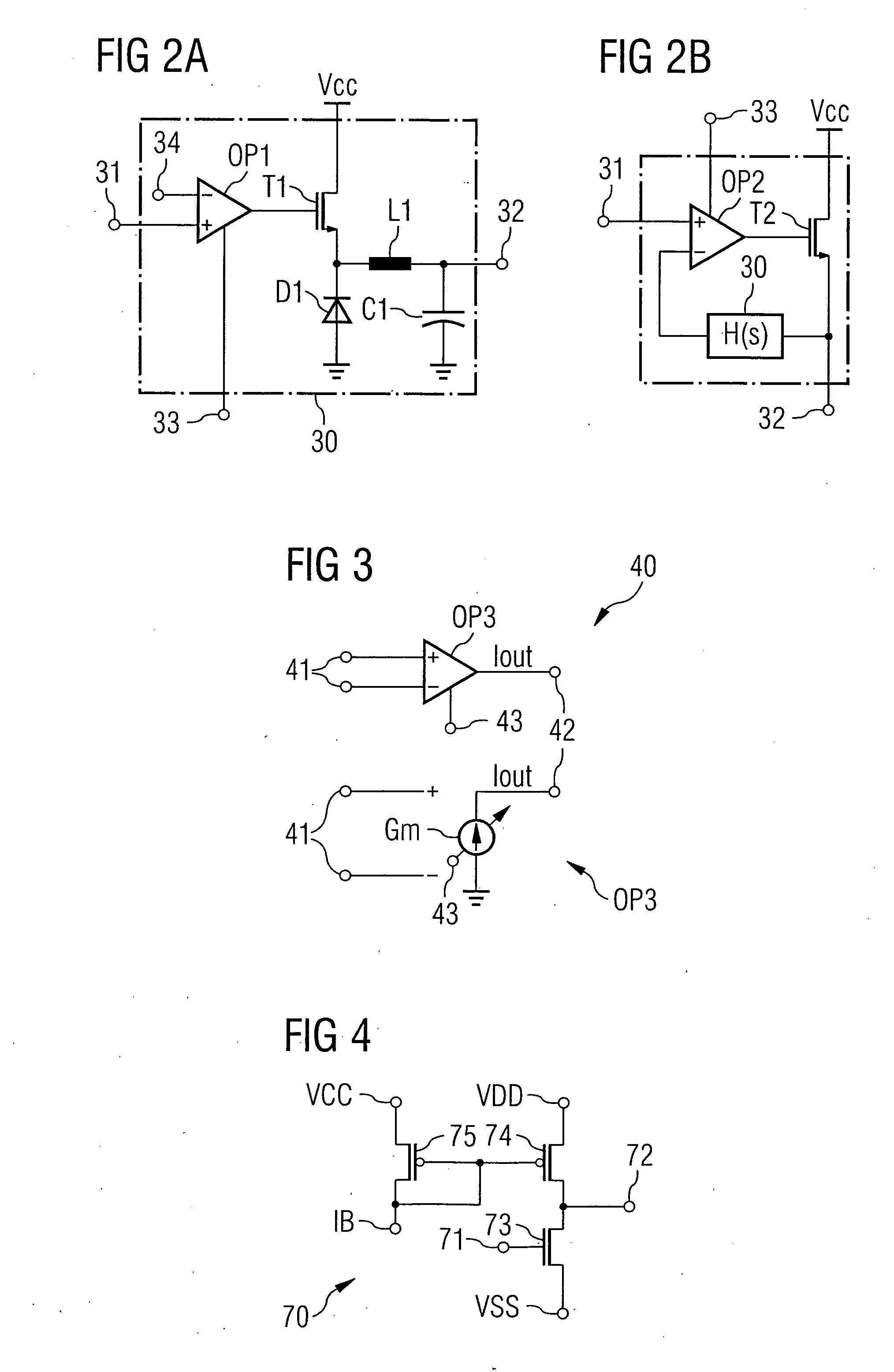
A modulator arrangement includes a power amplifier which receives a carrier signal and has a current control input and a voltage supply input. The modulator arrangement further includes a supply voltage modulator having an output coupled to the voltage supply input and an input coupled to the data input and a bias current modulator with an output coupled to the current control input and an input coupled to the data input. A control unit is provided which has a power control output coupled to the supply voltage modulator and to the bias current modulator to control the supply voltage modulator and the bias current modulator depending on a power control signal.

Description

FIELD OF THE INVENTION[0001]The invention relates to a modulator arrangement and to a method for signal modulation.BACKGROUND OF THE INVENTION[0002]The requirements for the signal quality of modulators, for example in transmitting devices, become more stringent as the need for high data rates and increasing mobility grows. The modern mobile radio standards such as universal mobile telecommunications system (UMTS), wideband code division multiple access (WCDMA), global system for mobile communication (GSM), enhanced data rates for GSM evolution (EDGE), Bluetooth medium data rate or Wireless local area network (WLAN) according to 802.11a / b / g require special modulation types for data transmission, which modulate, for example, both the phase and the amplitude of a carrier signal at the same time.[0003]Simultaneous amplitude and phase modulation make it possible to achieve higher data transmission rates and thus better bandwidth efficiency. The mobile radio standards mentioned above envi...

Claims


Application Information

Patent Timeline
IPC IPC(8): H03C3/00
CPCH03C5/00H03F3/24H03F1/0227
Inventor CEYLAN, NAZIMMULLER, JAN-ERIK
Owner INTEL CORP
Learn More