[0023] According to the present invention, by changing the subcarriers to which the first transmission power enabling the radio signals to reach all areas within a
cell, is set at a certain time interval, it is possible to configure a one-cell reuse system in which while using the same
frequency band as those of the adjacent
base station apparatus, they do not interfere with one another. Further, even if the propagation path characteristics are bad when transmitting the radio signals using the subcarriers in a specific
frequency band to which the first transmission power is set to one
mobile station apparatus, it is possible to transmit the radio signals to the above-mentioned
mobile station apparatus using the subcarriers in other frequency band to which the first transmission power is set as the subcarriers to which the first transmission power is set are changed at the certain time interval. Thereby, it is possible to use all frequency bands at all areas within the cell, enabling to perform the radio communication seamlessly. BEST
MODES FOR CARRYING OUT THE INVENTION
[0024] A radio communication system according to the present embodiment will be described herein after. The radio communication system includes a plurality of base
station apparatus and transmits radio signals to mobile
station apparatus existing within a cell configured by each base
station apparatus, using a multicarrier modulation system. Then, each base station apparatus sets to some subcarriers among all subcarriers a first transmission power (P1) enabling radio signals to reach all areas within the cell, and sets the subcarriers other than those to which the first transmission power is set, transmission power below second transmission power (P2) which is the maximum transmission power not interfering with adjacent cells. The amount of the transmission power set to each
subcarrier is previously determined as “transmission power profile”. In this embodiment, each base station apparatus changes the subcarriers to which the first transmission power (P1) enabling the radio signals to reach all areas within the cell is set to subcarriers having frequencies different from those of other base station apparatus constituting adjacent cells at the same
time of day at certain time interval. That is, each base station apparatus changes the transmission power profiles in which positions of the subcarriers to which the first transmission power is set are different from one another in a certain period at the same
time of day.
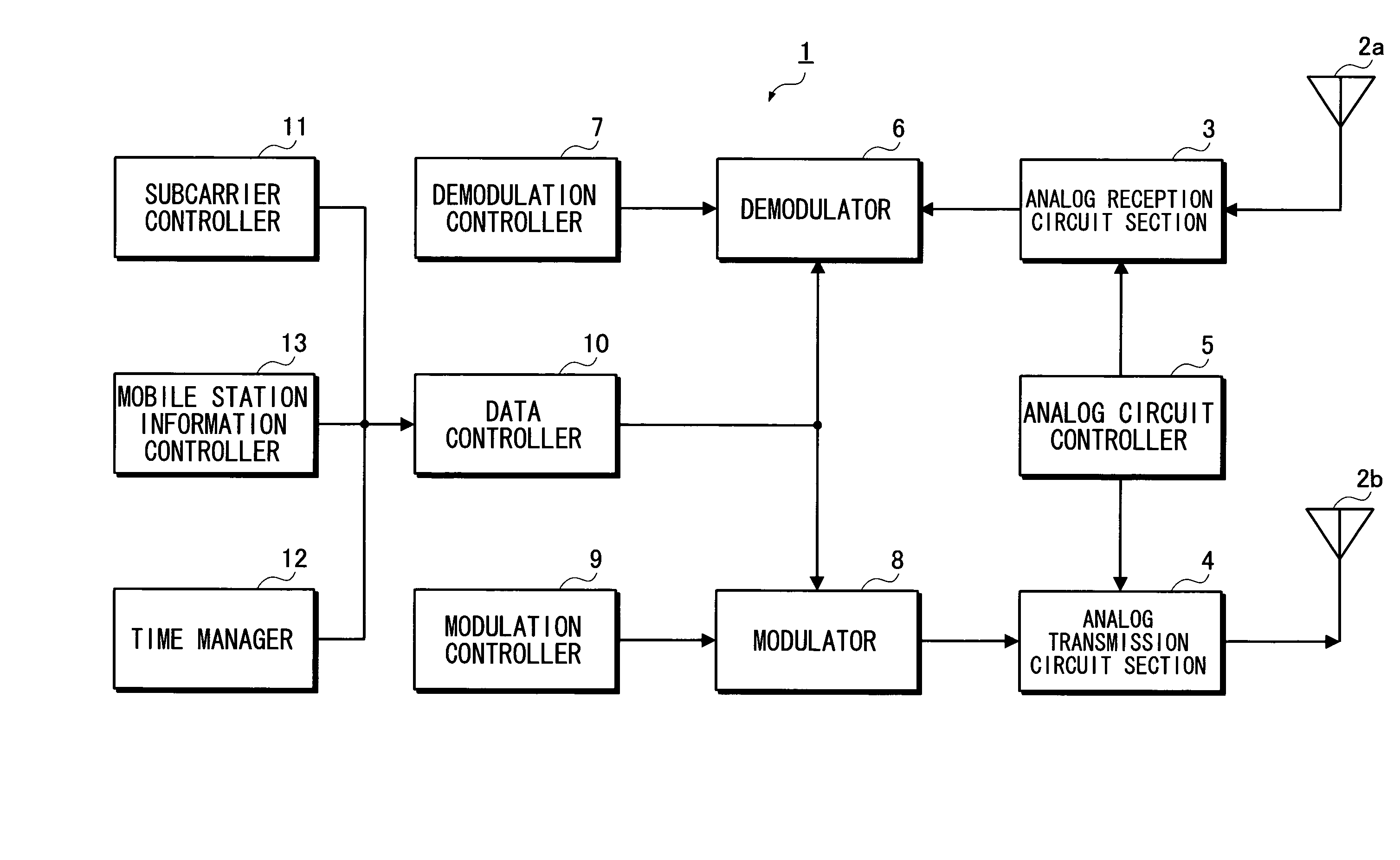
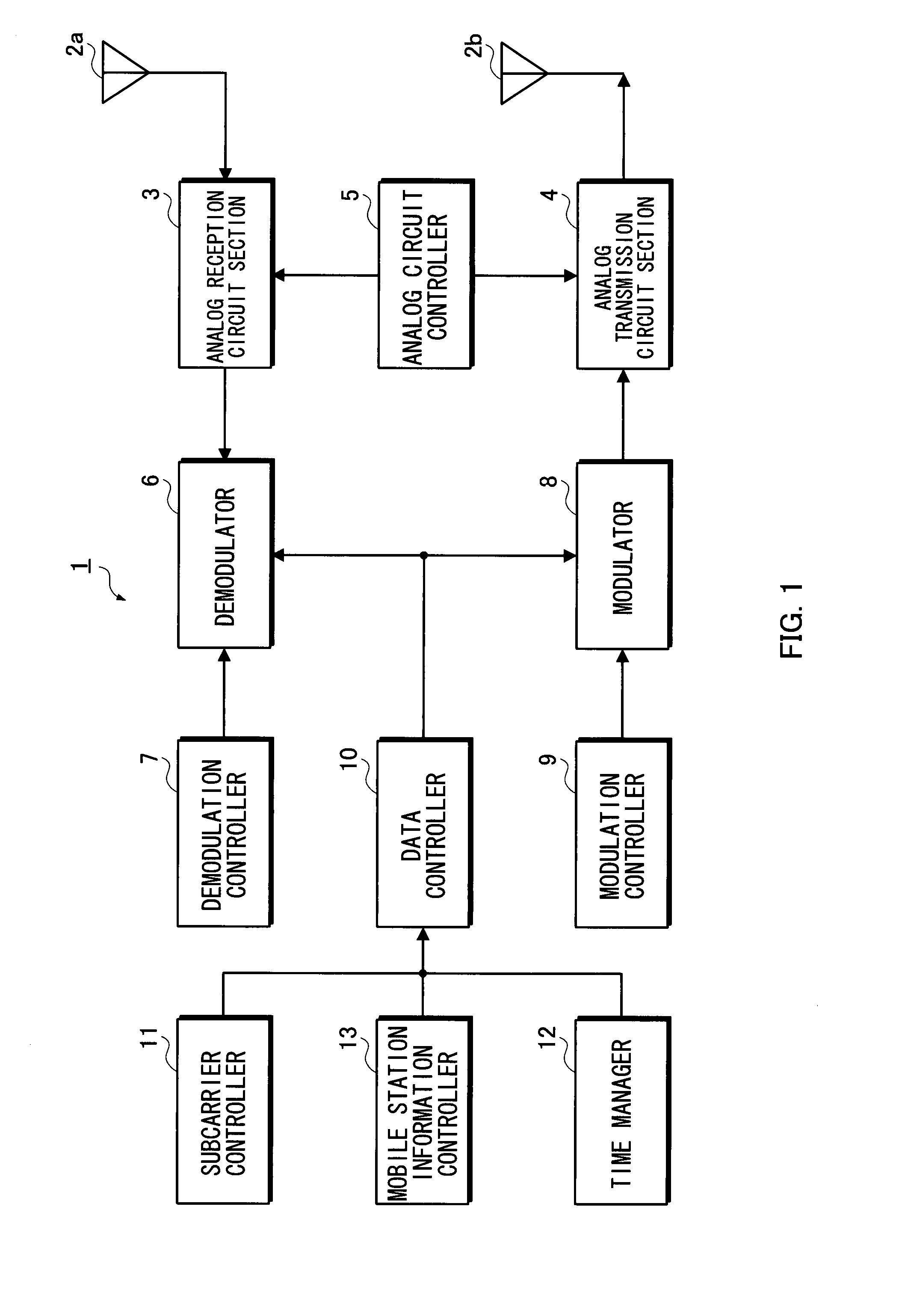
[0025]FIG. 1 is a
block diagram showing the outline configuration of the base station apparatus according to the present embodiment. As shown in FIG. 1, a base station apparatus 1 transmits / receives radio signals via a plurality of antennas (herein, two antennas) 2a and 2b. An analog reception circuit section 3 converts a received high-frequency
signal into a
digital signal. An
analog transmission circuit section 4 converts a
digital signal into a high-frequency
signal. An analog circuit controller 5 controls the analog reception circuit section 3 and the
analog transmission circuit section 4. A demodulator 6 is composed of a
digital signal processing circuit for
processing received data, and a
demodulation controller 7 controls the demodulator 6. In addition, a modulator 8 is composed of a
digital signal processing circuit for
processing transmission data, and a modulation controller 9 controls the modulator 8. A data controller 10 performs a control of transmission and reception data such as re-transmission and re-reception. A
subcarrier controller 11 controls transmission power of each
subcarrier and a user allocation and the like. A time manager 12 manages time and a mobile station information controller 13 manages the propagation path characteristics of each mobile station apparatus and the like. In addition, the antenna 2b, the
analog transmission circuit section 4, the modulator 8, the modulation controller 9, and the data controller 10 constitute a
transmitter, and the subcarrier controller 11 constitutes a transmission
power setting section. Further, a mobile station information controller 13 constitutes a
detector.
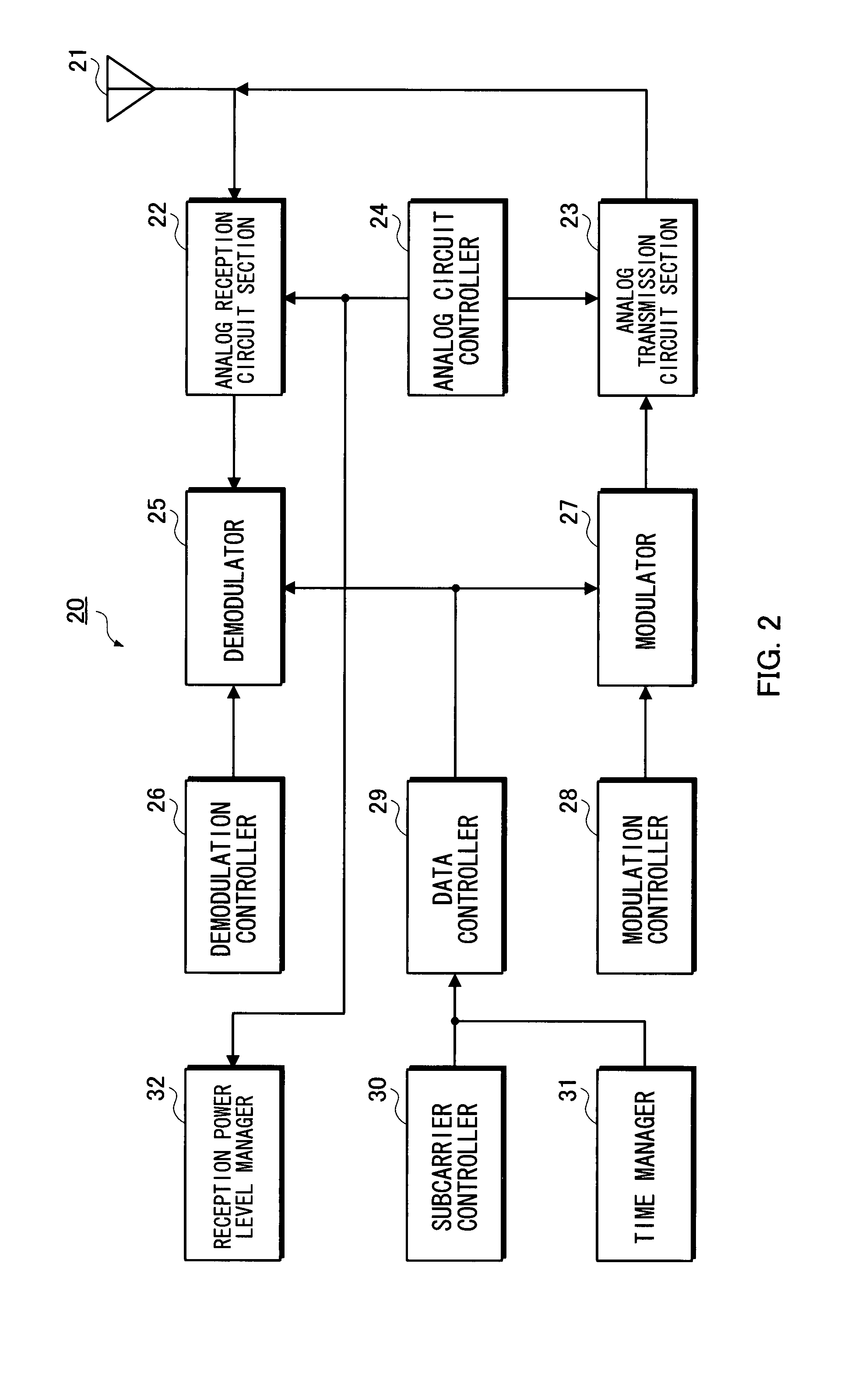
[0026]FIG. 2 is a
block diagram showing the outline configuration of the mobile station apparatus according to the present embodiment. As shown in FIG. 2, a mobile station apparatus 20 transmits / receives radio signals via one or more antennas (herein, one antenna) 21. An analog reception circuit section 22 converts a received high-frequency
signal into a digital signal. An analog transmission circuit section 23 converts a digital signal into a high-frequency signal. An analog circuit controller 24 controls the analog reception circuit section 22 and the analog transmission circuit section 23. A demodulator 25 is composed of a
digital signal processing circuit for processing received data, and a
demodulation controller 26 controls the demodulator 25. A modulator 27 is composed of a
digital signal processing circuit for processing transmission data, and a modulation controller 28 controls the modulator 27. A data controller 29 performs a control of re-transmission and re-reception and the like. A subcarrier controller 30 controls transmission power of each subcarrier, an allocation to mobile station apparatus and the like. A time manager 31 manages time and a reception
power level manager 32 manages reception power and the propagation path characteristics such as CINR.
[0027]FIG. 3 illustrates a state in which a plurality of the base station apparatus configures a plurality of cells. The figure exemplifies an arrangement of cells based on a
hexagonal cell generally used in a multi-
cell system. In addition, the present invention is not limited to a cell arrangement of this shape.
[0028] The radio communication system according to the present embodiment realizes the radio data communication in cells which use the same frequency band. The present invention can be applied to all cells and base station apparatus constituting the system. The present specification will describe, focusing on an operation of a “cell 1” shown in FIG. 3.

