
Vessel of a portable handheld work apparatus

Inactive Publication Date: 2008-04-17
ANDREAS STIHL AG & CO KG
View PDF17 Cites 7 Cited by
  • Summary
  • Abstract
  • Description
  • Claims
  • Application Information

AI Technical Summary

Benefits of technology

[0007]It is an object of the invention to improve a vessel of the kind described above so that an optical fill level detection is simplified while ensuring the liquid tightness.
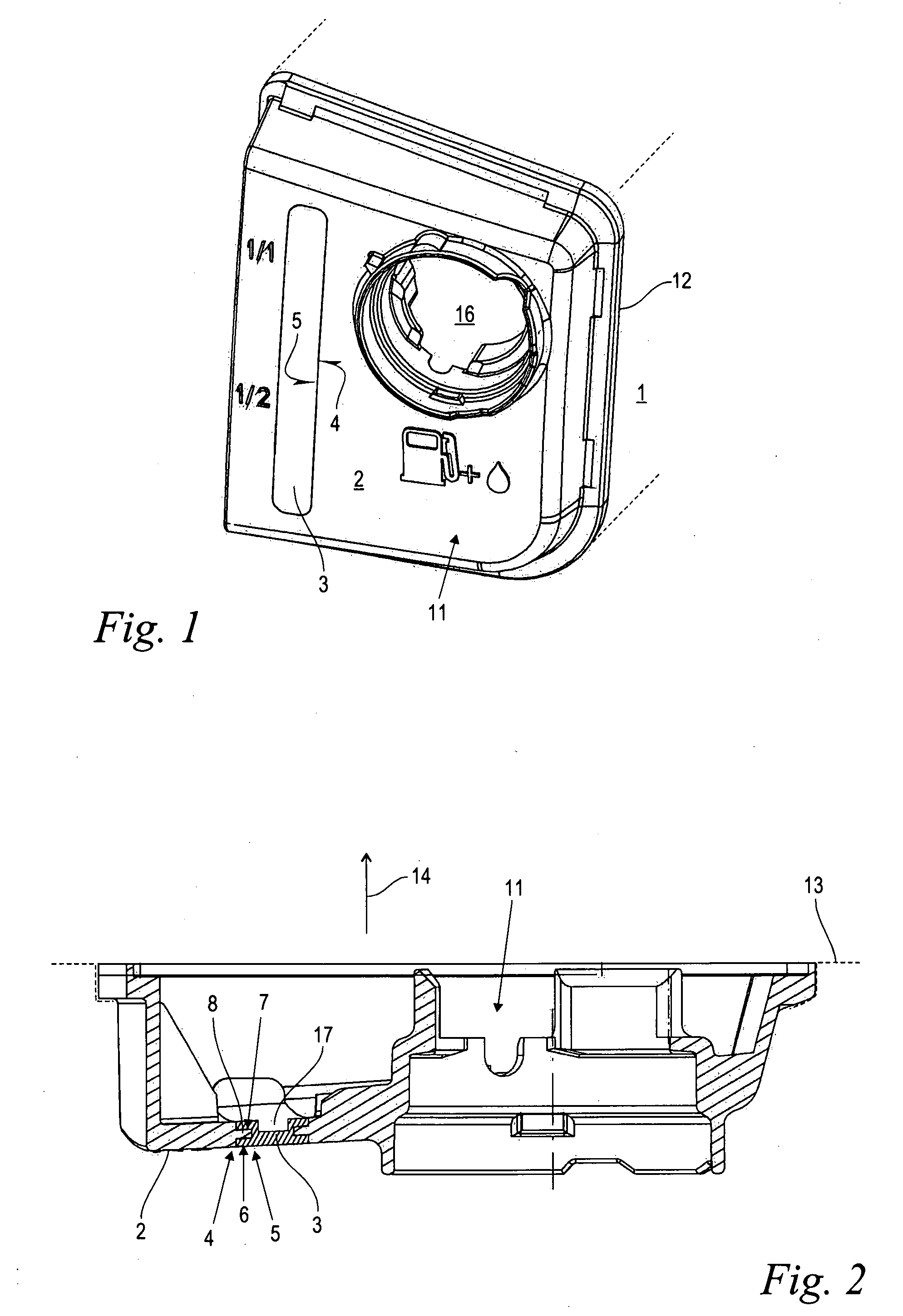
[0009]A vessel is suggested having a vessel wall and a viewing window configured as a two-component injection-molded part. Mutually adjoining edges of the vessel wall and the viewing window conjointly define a tongue-and-groove connection with at least one groove and at least one tongue. Preferably, the tongue-and-groove connection extends over the entire length of the mutually adjoining edges. The vessel wall can be injection molded from a structurally highly loadable, nontransparent plastic while the material selection for the likewise injection-cast viewing window can be selected exclusively in accordance with a viewpoint of good optical transmissivity. The arrangement has a high mechanical loading capacity. The structural material of the vessel wall can be easily and reliably connected to a further housing component by welding or the like. The tongue-and-groove connection between the vessel and the viewing window generates a large contact surface between the two different plastic materials of the vessel wall and the viewing window whereby a permanent liquid tight connection is ensured between the viewing window and the adjoining wall section. The injection-molded bond of the two materials, which occurs in the tongue-and-groove connection, furthermore exhibits a high carrying capacity.
[0011]The vessel wall with the integrated viewing window can be a classical two-component injection-molded part manufactured, for example, in accordance with the core-back process or the rotating plate process. The viewing window is advantageously configured as an insert part especially in the embodiment with a tongue-and-groove connection surrounding the entire periphery. The insert part is injection molded as a separate individual part and the material of the vessel wall is injected around the insert part. The insert part is produced in advance in a separate injection molding form wherein, with simple means, the formation of at least one groove and at least one tongue is possible. Thereafter, the viewing window in the form of an insert part is inserted, positioned and thereafter the structural material of the vessel wall is injected around the insert part by means of a suitable device in the injection molding form for the vessel wall. The injection molding form for the vessel part can also be configured simply and cost effectively in that sliders or the like are not required for the formation of the tongue-and-groove connection.
[0012]In a preferred further embodiment, the groove and the tongue extend in a surface pregiven by the vessel wall and the viewing window. The viewing window and the bordering region of the vessel wall exhibit essentially a constant thickness. The transverse cross sectional longitudinal axes of the groove and tongue lie parallel to the wall surface. Little space is needed especially in the direction of the wall thickness and high liquid tightness and mechanical loadability are combined with each other. Additional thickening in the connecting region is not required. A smooth surface results in the region of the connection which is free of thickness jumps. The arrangement is less sensitive with respect to contamination and can be easily cleaned.
[0014]To further increase the liquid tightness and the carrying capacity, a ratio of the width of the tongue to the width of the viewing window of at least 0.2 and a thickness of the portion bordering the groove of at least 0.2 mm has proven to be practical.
[0015]In an advantageous further embodiment, the viewing window has a recess with a thickness reduced compared to the edge region. It can also be practical that the viewing window is, in addition or alternatively to the recess, configured at least sectionally as a diffusing glass having a light diffracting surface structure arranged especially at the inner surface. In this way, the optical characteristics of the viewing window improve still further and therefore the readability of the fill level of the vessel is further improved.

Problems solved by technology

The transparency of suitable plastic is, however, limited.
The requirement of transparency limits the selection of materials whereby the mechanical loading capacity is limited.
A liquid tight and mechanically loadable connection or bond of the transparent vessel part to an adjacent housing part, which forms section-wise a part of the vessel, is difficult to realize.

Method used


Image

  • Vessel of a portable handheld work apparatus
  • Vessel of a portable handheld work apparatus
  • Vessel of a portable handheld work apparatus

Examples


Embodiment Construction

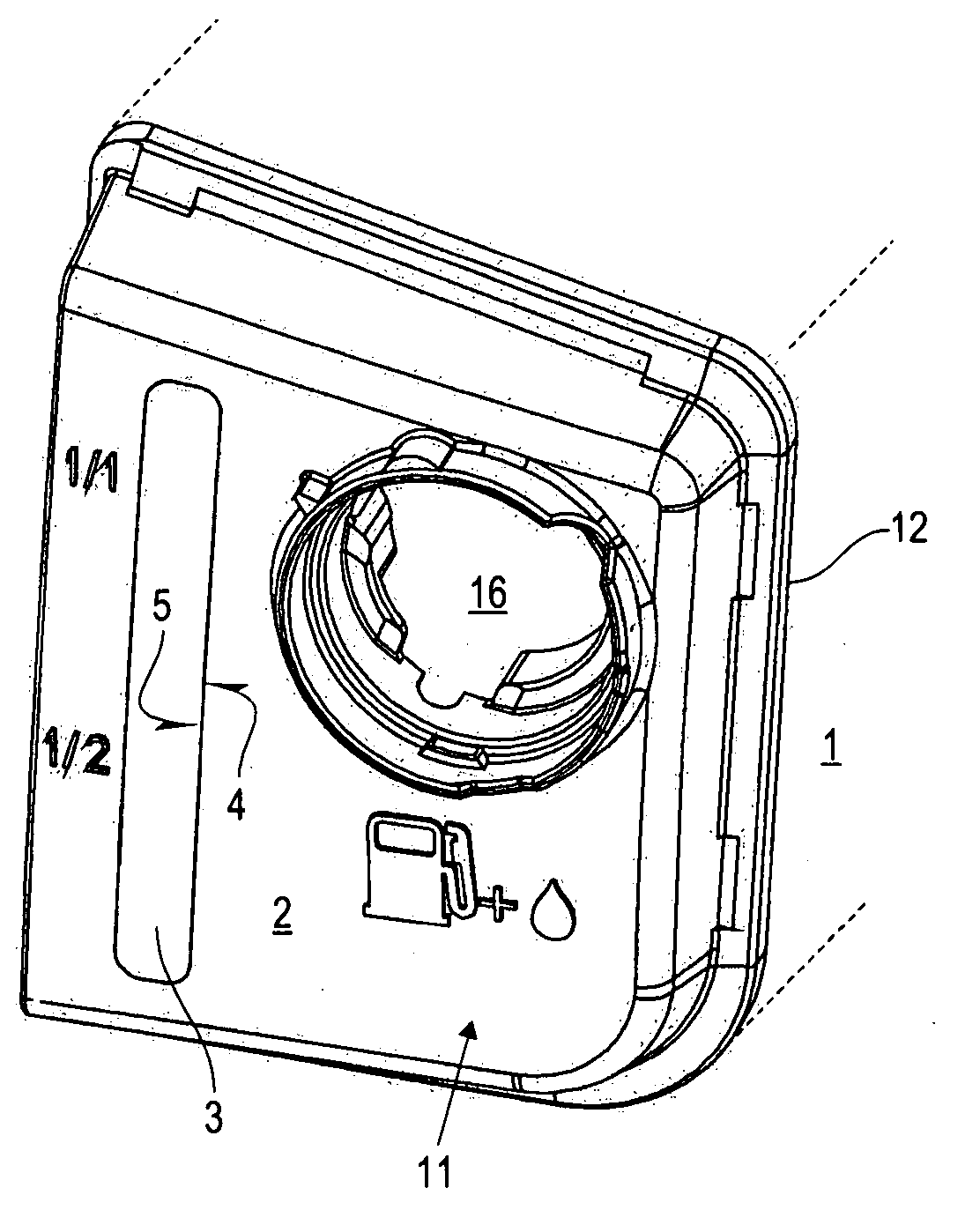
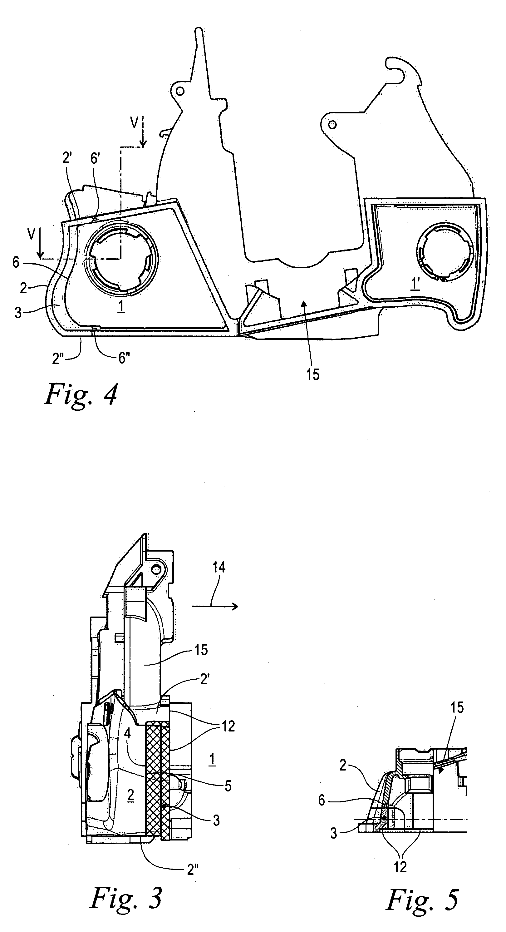
[0024]FIG. 1 shows a perspective view of a vessel 1 of a portable handheld work apparatus such as a cutoff machine or the like. The vessel 1 is for liquid operating substances such as fuel, oil or the like. Part of the vessel 1 is a cover part 11 configured as a two-component injection-molded part wherein a venting opening 16 as well as a viewing window 3 are arranged in the end face vessel wall 2. In the embodiment shown, the vessel 1 is provided for accommodating a fuel / oil mixture for supplying a loss-lubricated internal combustion engine of the work apparatus. The fuel / oil mixture is filled via the fill opening 16 into the vessel 1. The fill opening 16 is thereafter closed by a cap (not shown). The fill level of the operating substance in the vessel 1 can be detected via the transparent viewing window 3 and can be controlled in this manner.

[0025]FIG. 1 shows that the elongated viewing window 3 has a peripherally-extending edge 5 on which the edge 4 of the adjoining region of the...


PUM


Abstract

A vessel (1) of a portable handheld work apparatus is provided for liquid operating substances such as fuel, oil or the like. The vessel (1) has a vessel wall (2) of injection-molded plastic and a viewing window (3) integrated into the vessel wall (2). The viewing window is provided for viewing the fill level. The vessel wall (2) and the viewing window (3) are configured as a two-component injection-molded part. Mutually adjoining edges (4, 5) of the vessel wall (2) and the viewing window (3) have a tongue-and-groove connection (6) with at least one groove (7) and at least one tongue (8).

Description

CROSS REFERENCE TO RELATED APPLICATION[0001]This application claims priority of German patent application no. 10 2006 048 550.5, filed Oct. 13, 2006, the entire content of which is incorporated herein by reference.FIELD OF THE INVENTION[0002]The invention relates to a vessel of a portable handheld work apparatus for liquid operating substances such as fuel or the like.BACKGROUND OF THE INVENTION[0003]Handheld portable work apparatus such as chain saws, cutoff machines or the like have one or several vessels for liquid operating substances. These vessels hold fuel for an internal combustion engine of the work apparatus, oil for the saw chain of a chain saw or the like.[0004]A control of the fill level of the operating liquid in the vessel is necessary from time to time. This can take place, for example, with a dipstick. Especially vessels having a vessel wall of injection-molded plastic with a viewing window integrated into the wall of the vessel are provided for viewing the fill lev...

Claims


Application Information

Patent Timeline
IPC IPC(8): G01F23/02
CPCF01M2011/0091F01M11/0004
Inventor GWOSDZ, FABIANSCHLOSSARCZYK, JORG
Owner ANDREAS STIHL AG & CO KG
Learn More