Splicing Tape

a technology of splicing tape and adhesive, applied in the direction of film/foil adhesive, photosensitive materials, instruments, etc., can solve the problems of insufficient control of the strength of the cleavable layer, no splicing, waste of 2% of the material on each roll, etc., and achieve the effect of low surface energy and high surface energy

Inactive Publication Date: 2008-04-17
CUSTOM ADHESIVE PRODS
View PDF22 Cites 16 Cited by
  • Summary
  • Abstract
  • Description
  • Claims
  • Application Information

AI Technical Summary

Benefits of technology

[0013]Another embodiment is a method for forming a splicing tape for use between two rolls. The method includes steps of furnishing a first film having a high surface energy, applying a second film to the first film, said second film configured as a polymeric film, applying a third film to the second film, said third film having a low surface energy, applying an adhesive coating to exposed surfaces of the first and third films, and applying a release liner to the splicing tape, wherein the first film splits easily from the second film, or the second film splits easily from the third film, when a splice is made between the two rolls.

Problems solved by technology

It has been estimated that about 2% of the material on each roll is wasted because of the technical requirements for making even these splices.
This does not sufficiently control the strength of the cleavable layer, and the adhesive tape may break before the paper cleaves, and no splice is achieved.
This adhesive tape is not ideal because the backing layer, which is cleavable, is not sufficiently controlled and the force required may vary from splice to splice.
This leads to unpredictability in the breakaway and makes this product more difficult to use,
While this process works, it is expensive to have perforations and two separate layers of adhesive on the bottom portion.

Method used


Image

  • Splicing Tape
  • Splicing Tape
  • Splicing Tape

Examples


Embodiment Construction

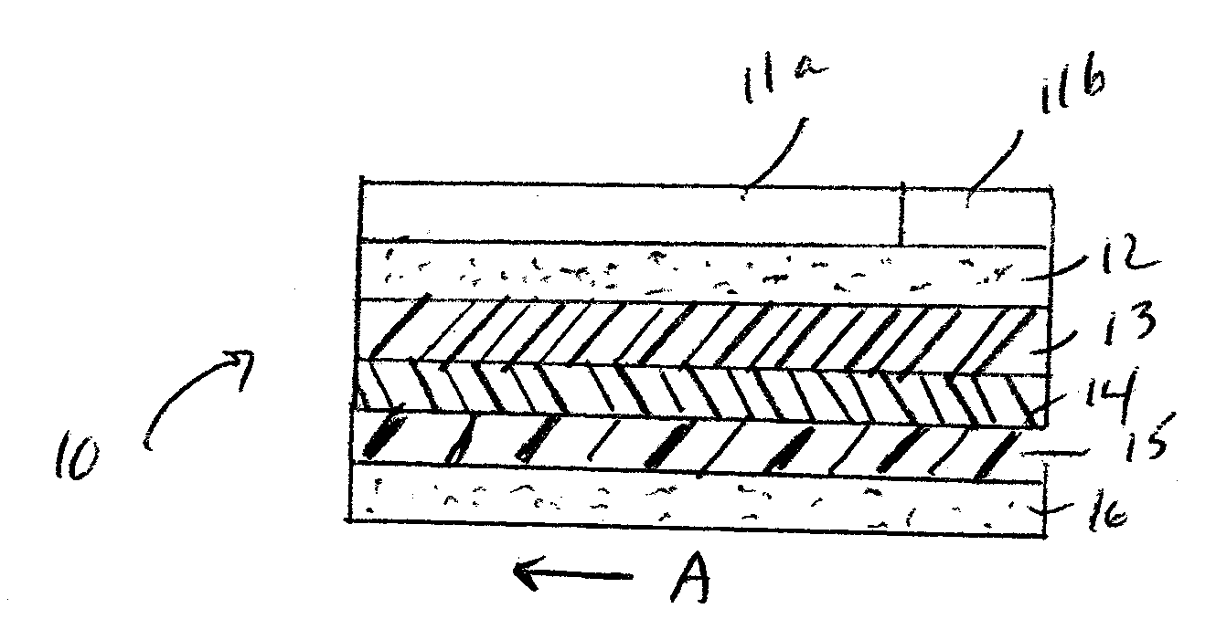
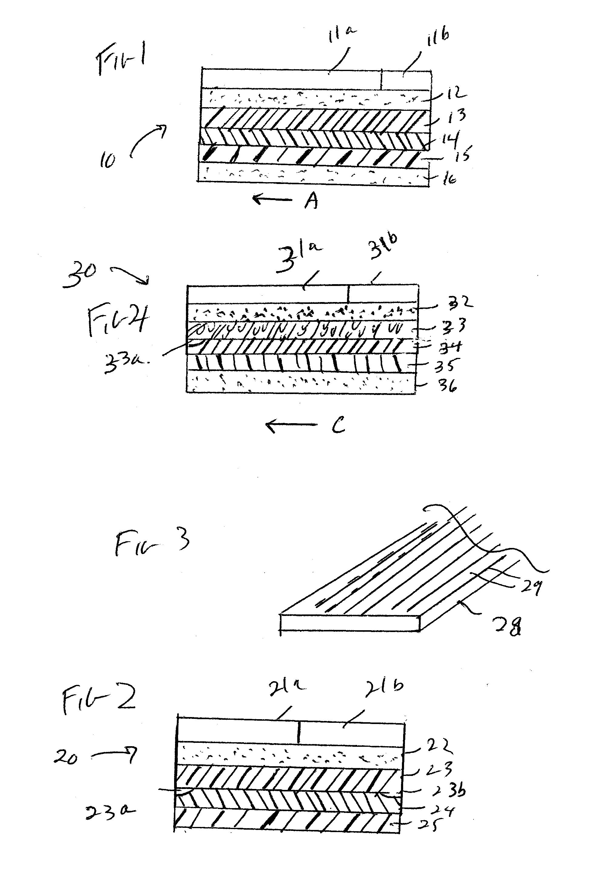
[0022]Web-fed processes may run at speeds of greater than 1200 meters per minute (about 4000 feet per minute). Continuous, reliable production demands that the process, usually a printing or a coating process, run uninterrupted for as long a period of time as possible. Running at such high speed also means that it may be both difficult and essential to change from the running roll to a replacement roll with virtually no interruption, as described above.

[0023]The process for making the change generally takes place with embodiments of the invention as follows. A replacement roll is readied for its place in the line by placing a splicing tape between its top layer and its second layer. The bottom layer of the splice is adhered to the second layer of the roll, and a portion of the release liner of the splice, the portion nearer the trailing edge, is removed. The top layer of the replacement roll is adhered to the exposed portion of the adhesive. When the end of the running roll nears, t...


PUM

PropertyMeasurementUnit
thicknessaaaaaaaaaa
surface energyaaaaaaaaaa

Abstract

A splicing tape for making a running splice is disclosed. A running splice is needed for web-fed type continuous processes involving rolls of material. Materials are typically paper or thermoplastic rolls to be printed or coated. The layered splicing tape includes three central layers or films with a controlled breaking force that allows better control over the force required to separate the central layers and allow a replacement roll to be fed into the web on the tail of the roll that has almost been consumed. Pressure-sensitive or other adhesives adhere the splice to the roll and the cohesive failure of the splice then enables the splice to be made without stopping the process.

Description

CROSS-REFERENCE TO RELATED PATENT APPLICATIONS[0001]This patent application claims the benefit of U.S. Provisional Patent Application No. 60 / 829,427, filed Oct. 13, 2006, the entire disclosure of which is incorporated by reference in its entirety herein.FIELD OF THE INVENTION[0002]This invention generally relates to pressure sensitive adhesive systems and polymeric films, and the application of pressure sensitive adhesives and polymeric films to on-the-fly splices for industrial web processes.BACKGROUND OF THE INVENTION[0003]There are many continuous web-fed processes, in which paper or thin plastic film is unwound from a roll and fed into a printer or coating machine to print or coat the incoming material. Such processes are preferably run in a continuous, uninterrupted manner, even though the feed rolls will eventually be consumed. To keep the presses or coaters running, it is desirable that a splice be made from the roll already in the process to the next roll. A splice may be an...

Claims


Application Information

Patent Timeline
Patent Type & Authority Applications(United States)
IPC IPC(8): B65H19/00C09J7/29
CPCB65H19/102C09J7/0296C09J2201/162C09J2203/342Y10T428/1476C09J2401/006C09J2423/006C09J2467/006C09J2400/283C09J7/29C09J2301/162
Inventor MANTEUFEL, TODD L.
Owner CUSTOM ADHESIVE PRODS
Why Eureka
Try Eureka