Method and Processor for Power Analysis in Digital Circuits

a power analysis and digital circuit technology, applied in the direction of cad circuit design, program control, instruments, etc., can solve the problems of inability to accurately determine spatial and temporal correlation, contribute significantly to power consumption, and inconvenient computation, etc., to achieve accurate analysis, not computationally expensive, and accurate analysis

Inactive Publication Date: 2008-04-17
UNIV COLLEGE DUBLIN NAT UNIV OF IRELAND DUBLIN
View PDF14 Cites 44 Cited by
  • Summary
  • Abstract
  • Description
  • Claims
  • Application Information

AI Technical Summary

Benefits of technology

[0030]A method of determining the power dissipation characteristics of a digital circuit in which the method further comprises the step of storing a record of all transitions in a primitive types output over a simulation time unit (STU) and calculating the toggle dynamic power consumption for that primitive type. In this way, it will be possible to calculate the toggle power for a device which was heretofore not possible using the existing systems and methods. This will enable a more accurate analysis to be carried out.
[0031]A method of determining the power dissipation characteristics of a digital circuit in which the method further comprises the step of determining the nature of the transition of the output and thereafter calculating the dynamic power consumption based on the nature of the transition. This is seen as useful as the transition dynamic power may differ from a 0 to 1 transition to a 1 to 0 transition and therefore a more accurate analysis is possible.
[0032]A method of determining the power dissipation characteristics of a digital circuit in which the method further comprises the step of storing a record of all input gate values for a primitive type and calculating the leakage power consumption for that primitive type. Again, by storing the values of the inputs, it is possible to calculate the values of static or leakage power dissipation in a simple manner that is not computationally expensive.

Problems solved by technology

There are however, problems associated with each of these methods.
Other techniques in this category are based on Binary Decision Diagrams (BDDs) and Boolean Differences, these are computational prohibitive for large circuits containing hundreds of thousands of gate circuits.
Spatial and Temporal correlation is also difficult to determine for circuits using probability techniques and may contribute significantly to the power consumption.
Both of these entities ignore circuit delays and consequently these measures are not suitable for estimating toggle power.
In general, the accuracy in power estimates delivered by these methods is limited by the quality of the delay models and the reality of the input specified.
The major issues in these techniques are the speed of computation and the selection of input vectors which permit the calculated average power to converge close enough to the true average power.
However, it may require several thousand cycles to calculate accurately the average power of individual modules in the circuit.
While the actual computations of these methods are relatively fast, the results of the probabilistic methods are typically in a window having an error margin of between 10% and 80%.
More accurate statistical techniques involving gate level simulation are possible but they are heretofore not realistically feasible due to the enormous computational load for large circuits.
Another problem associated with determining the power dissipation characteristics in a digital circuit arises out of the nature of the circuits themselves.
These devices only consume power through output transitions.
However, in order to maintain or improve circuit speed, the ratio of supply voltage to threshold voltage must be 5 or greater otherwise the current drive capability of the gates is severely diminished.
Thus, the threshold voltage is reduced with the unfortunate side-effect that there is a large increase in standby current, otherwise referred to as Leakage Current.
For ultra deep submicron devices Gate oxide tunneling is a significant contributor to leakage current.
Therefore, in the simulation process, it is not possible to determine leakage current through the detection of output transitions, but rather through the determination of the input state of each device.
While, this techniques has cited benchmarks that are accurate to within 2% of values calculated by other design tools, average errors are 10-20% and in some cases the error has been in excess of 80%.

Method used


Image

  • Method and Processor for Power Analysis in Digital Circuits
  • Method and Processor for Power Analysis in Digital Circuits
  • Method and Processor for Power Analysis in Digital Circuits

Examples


Embodiment Construction

[0075]The invention will now be more clearly understood from the following description of some embodiments thereof, given by way of example only in which:

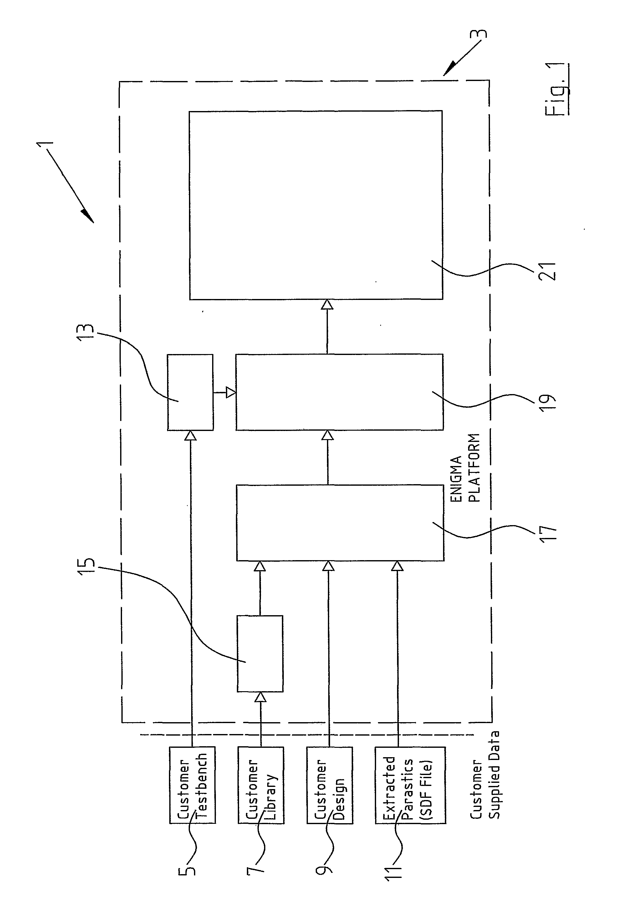
[0076]FIG. 1 is system overview of a system in which the analysis of digital circuits may be carried out;

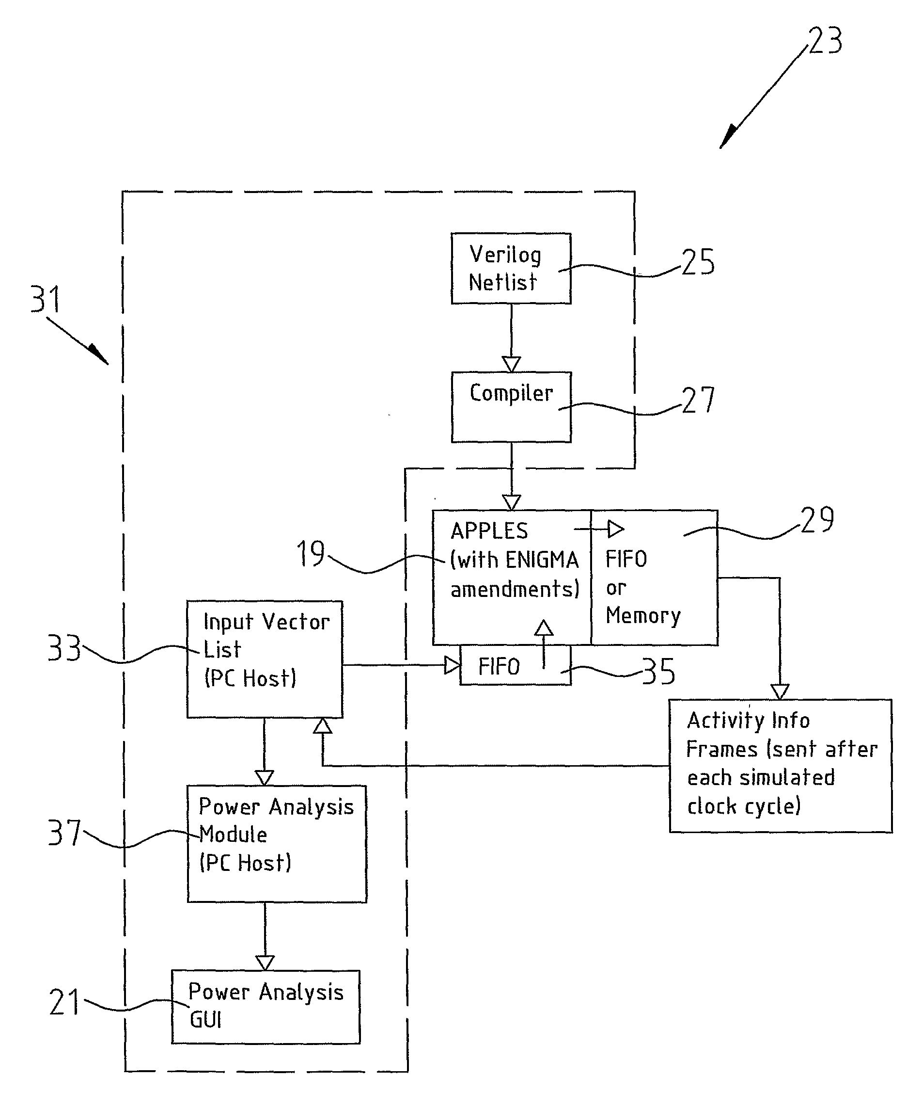
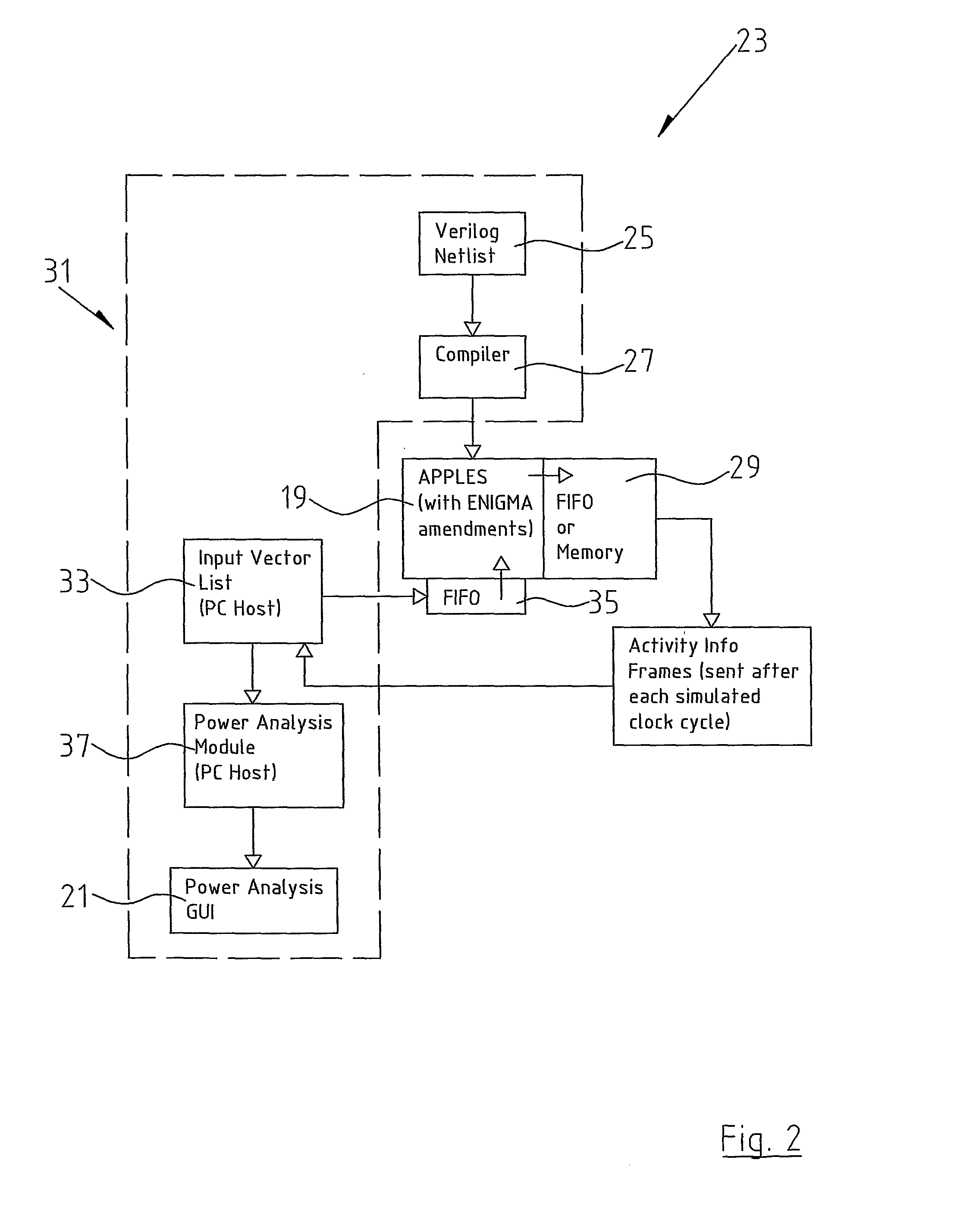
[0077]FIG. 2 is a block diagram of a system in which the analysis of digital circuits may be carried out incorporating the processor according to the present invention;

[0078]FIG. 3 is a block diagram of an alternative system incorporating the processor according to the present invention;

[0079]FIG. 4 is a block diagram of the additional registers incorporated into the processor of the present invention;

[0080]FIG. 5 is a component diagram of a complex cell which may be modeled using the method according to the invention;

[0081]FIG. 6 is a block diagram of a typical design methodology with the processor and method according to the invention incorporated in the design flow; and

[0082]FIG. 7 is a block diagram of a processor with assoc...


PUM


Abstract

This invention relates to a method and processor (19) for power analysis in digital circuits. The method incorporates a main processor (19) and an associative memory mechanism (101a, 101b, 102, 104, 105, 106), the associative memory mechanism comprising a plurality of associative arrays (101a, 101b), an input value register (102), at least one result register (104) and a memory block area (29). A circuit design is transformed into a functionally equivalent model format suitable for processing in the associative array and thereafter input vectors are applied to the circuit and a record is kept of the inputs and or the outputs on each of the gates in the circuit over a specified time period. In this way, it is possible to calculate the leakage power dissipation as well as both the toggle dynamic power and the transition dynamic power.

Description

[0001]This invention relates to a method and a processor for determining the power dissipation characteristics in a digital circuit.[0002]One of the most important considerations when designing digital circuits is the power consumption and more specifically the power dissipation characteristics of that digital circuit. The power dissipation characteristics are central to the design of many digital circuits as they determine amongst other things the power supply that will be required to operate the circuit as well as the amount of heat that will be generated by that circuit. Many of these digital circuits may be implemented in mobile applications such as mobile telephony whereby the amount of power drawn off a battery supply is crucial in the design process. It is therefore vital to be able to accurately simulate the power dissipation characteristics of a particular circuit design before going to the effort and expense of realizing that circuit and subsequently carrying out tests the...

Claims


Application Information

Patent Timeline
Patent Type & Authority Applications(United States)
IPC IPC(8): G06F17/50
CPCG06F2217/78G06F17/5022G06F30/33G06F2119/06
Inventor DALTON, DAMIAN JUDELEENEY, HUGO MICHAELVADHER, ABHAY
Owner UNIV COLLEGE DUBLIN NAT UNIV OF IRELAND DUBLIN
Why Eureka
Try Eureka