Supercharge Your Innovation With Domain-Expert AI Agents!

High Density IC Module

a high-density, ic module technology, applied in the direction of semiconductor devices, semiconductor/solid-state device details, electrical apparatus, etc., can solve the problems of complex structure with attendant scalability, construction technique complexity, etc., to facilitate bonding of the second die, improve heat transfer to the substrate, and improve signal integrity

Active Publication Date: 2008-04-24
STAKTEK GROUP LP
View PDF8 Cites 0 Cited by
  • Summary
  • Abstract
  • Description
  • Claims
  • Application Information

AI Technical Summary

Benefits of technology

[0008]In some embodiments, bonding pads are disposed between the substrate and the second die within the perimeter of the first mounted die. In other embodiments, a single set of pads may be bonded to bumps on two separate dice through openings in the substrate. Alternatively, the first and second die are bonded to the substrate using complimentary aligned bonding pads connected by conductive vias through the substrate. Pad-to-pad or dual bump-to-pad mounting improves signal integrity by eliminating the need for conventional forked conductive traces.
[0009]Still, in other embodiments, a first mounted die may be used to heat the substrate to facilitate bonding of the second die. Compression forces and / or ultrasonic vibrations with or without heating the second die may then be applied in combination with the heat from the first die to bond the second die. A thermally conductive underfill material may be used to improve heat transfer to the substrate.
[0010]TC / TS bonding of DRAM die according to various embodiments of the present invention provides substantial improvements in signal integrity and cost of manufacturing compare to conventional wire bonding. Additionally, the overall profile of the mounted parts is lower and it may not be necessary to mold over the mounted part, since there are no wires to protect. TC / TS bonding can also provide lower temperature bonding and can be used at tighter pitches than conventional assembly processes.

Problems solved by technology

Most previous systems that employ unpackaged die have provided complex structures with attendant scalability and construction technique complexities.

Method used


Image

  • High Density IC Module
  • High Density IC Module
  • High Density IC Module

Examples


Embodiment Construction

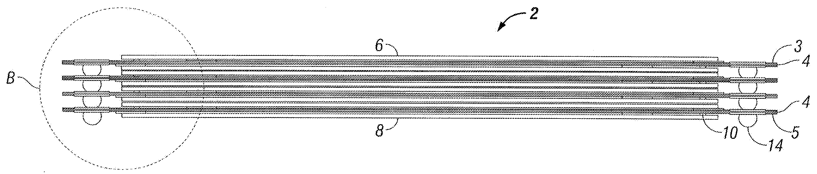
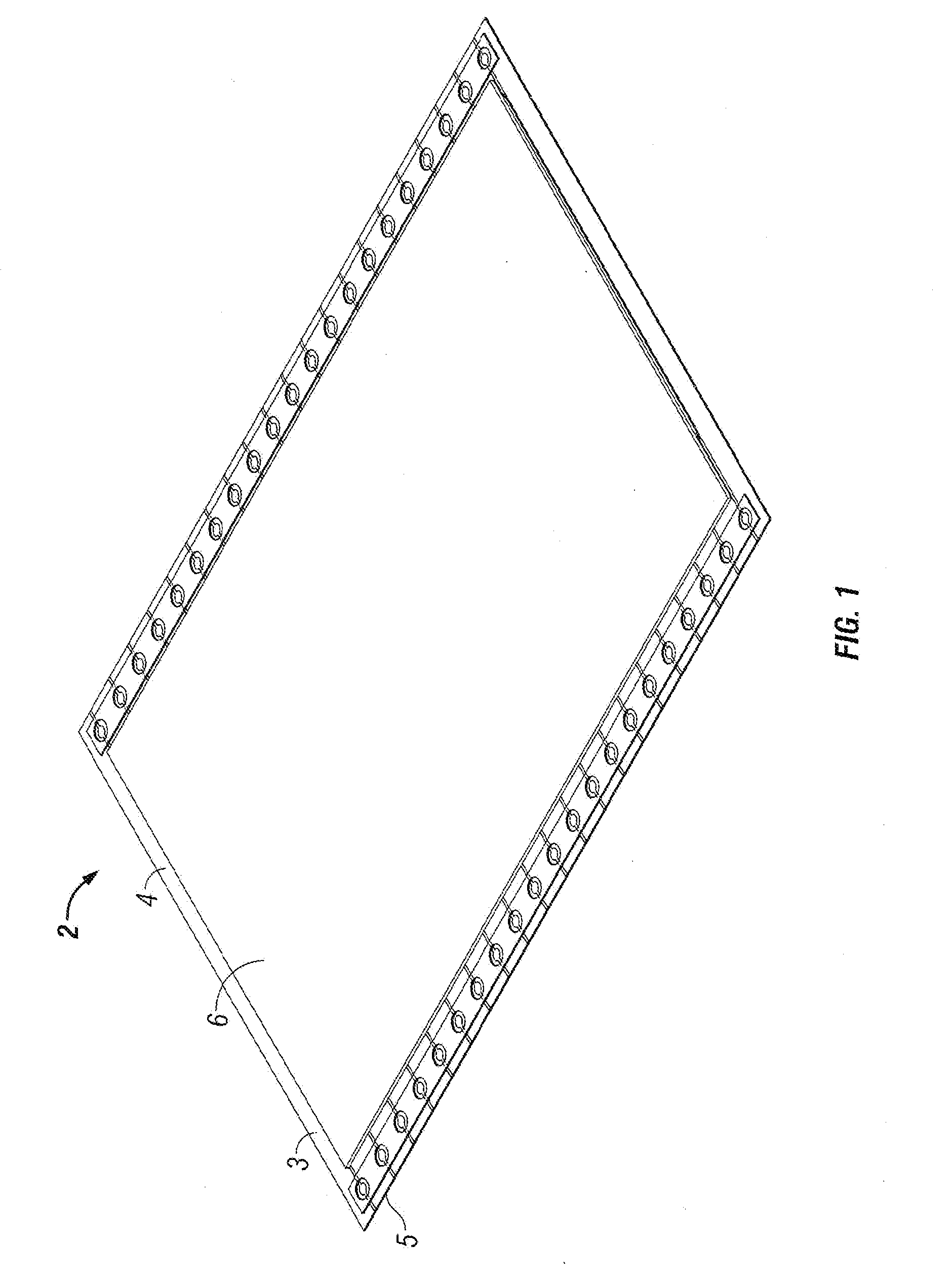
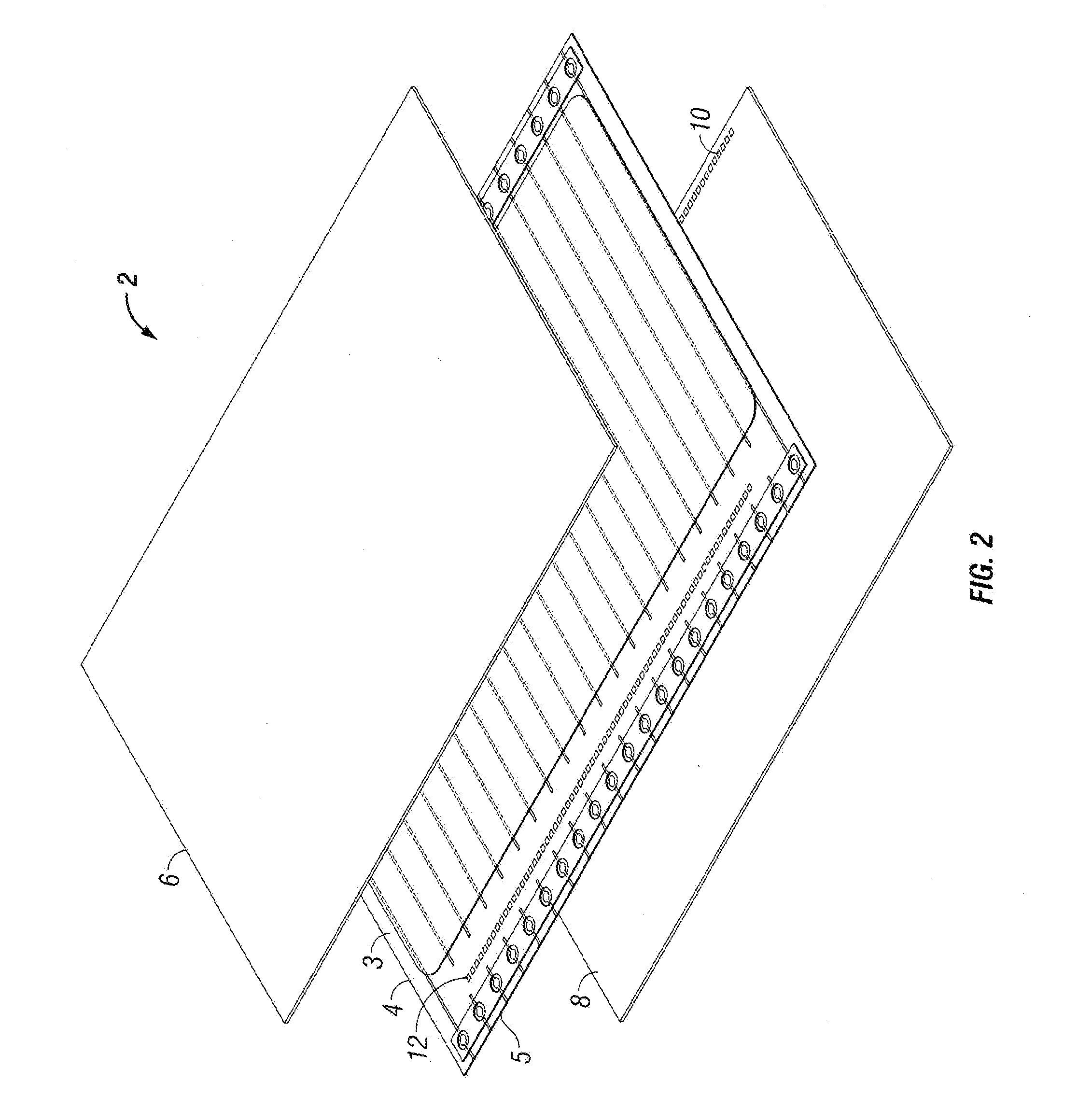
[0020]In accordance with various aspects of the present invention, a dual-die IC configuration is provided for use in IC packages. The present invention may be used to form any number of stacked or non-stacked IC packages using any number of bonding techniques. That being said, the present invention is described herein in the exemplary context of thermocompression bonding and / or thermosonic bonding of die to substrates for use in stacked flash and DRAM IC packages.

[0021]The term “substrate” as described herein may include, but is not necessarily limited to, a redistribution substrate useful in forming stacked integrated circuit packages. The substrate may be of any shape or size and in general, may be constructed from a wide variety of materials including, but not necessarily limited to, flex (generally polyimide-based), FR4, BT resin, alumina, silicon, glass epoxy, polyimide, polycarbonate, and the like. One possible substrate for die mounting and interconnect is a 1 metal layer fl...


PUM


Abstract

A system a method for assembling dual-die integrated circuit packages using thermocompression bonding or thermosonic bonding to bond a second die to a substrate opposite a first die bonded to the substrate. The second die is bonded using heat conducted through the first die to the substrate, and optionally through an underfill material. The first and second die are connected such that bumps are connected to common bonding pads on the substrate. Bumps on one of the die extend through openings in the substrate to connect to the common bonding pads. The bonding pads are within the perimeter of the first die.

Description

CROSS-REFERENCE TO RELATED APPLICATIONS[0001]This application claims priority to provisional application No. 60 / 862,431 filed Oct. 20, 2006, pending, which is hereby incorporated by reference,TECHNICAL FIELD[0002]The present invention generally relates to integrated circuits and, in particular, to bonding of multiple die on substrates for use in stacked integrated circuit packages.BACKGROUND OF THE INVENTION[0003]A variety of techniques are used to stack integrated circuits into a module. Some require that the circuits be encapsulated in special packages, while others use circuits in conventional packages. Both leaded and BGA type packaged integrated circuits (ICs) have been stacked. Although BGA packaging has become widely adopted, leaded packages are still employed in large volumes in low cost applications such as, for example, flash memory, which, when packaged, is typically found in thin small outline packages otherwise known as TSOPs.[0004]Other technologies have been devised t...

Claims


Application Information

Patent Timeline
IPC IPC(8): H01L23/48H01L21/58
CPCH01L23/5387H01L2924/01327H01L24/90H01L25/0657H01L2224/81203H01L2224/81205H01L2224/81801H01L2224/90H01L2225/06517H01L2225/0652H01L2225/06572H01L2225/06582H01L2225/06589H01L2924/09701H01L24/81H01L2924/14H01L2924/00
Inventor PARTRIDGE, JULIANSZEWERENKO, LELANDWEHRLY, JAMES DOUGLAS
Owner STAKTEK GROUP LP
Features
  • R&D
  • Intellectual Property
  • Life Sciences
  • Materials
  • Tech Scout
  • Unparalleled Data Quality
  • Higher Quality Content
  • 60% Fewer Hallucinations
Learn More