Electric Vehicle System for Charging and Supplying Electrical Power

a technology for electric vehicles and charging devices, applied in the direction of electric devices, motors/generators/converter stoppers, dynamo-electric converter control, etc., can solve the problems of battery only providing a very limited driving distance, few miles, and devices cannot operate as power sources to supply external loads

Inactive Publication Date: 2008-04-24
UT BATTELLE LLC
View PDF13 Cites 65 Cited by
  • Summary
  • Abstract
  • Description
  • Claims
  • Application Information

AI Technical Summary

Problems solved by technology

As such, the batteries can only provide a very limited driving distance (a few miles) in the electrical only mode, in which the engine is not used.
This device, however, cannot operate as a power source to sup

Method used


Image

  • Electric Vehicle System for Charging and Supplying Electrical Power
  • Electric Vehicle System for Charging and Supplying Electrical Power
  • Electric Vehicle System for Charging and Supplying Electrical Power

Examples


first embodiment

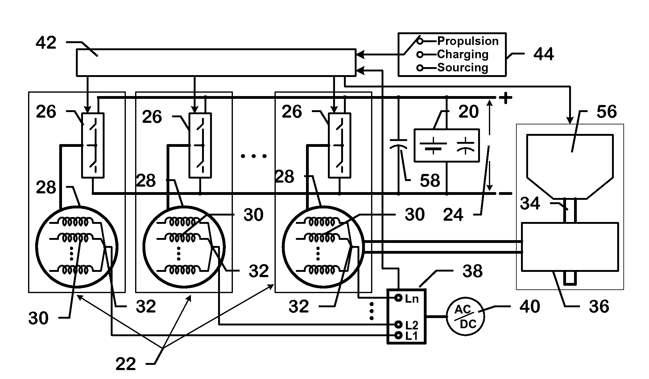
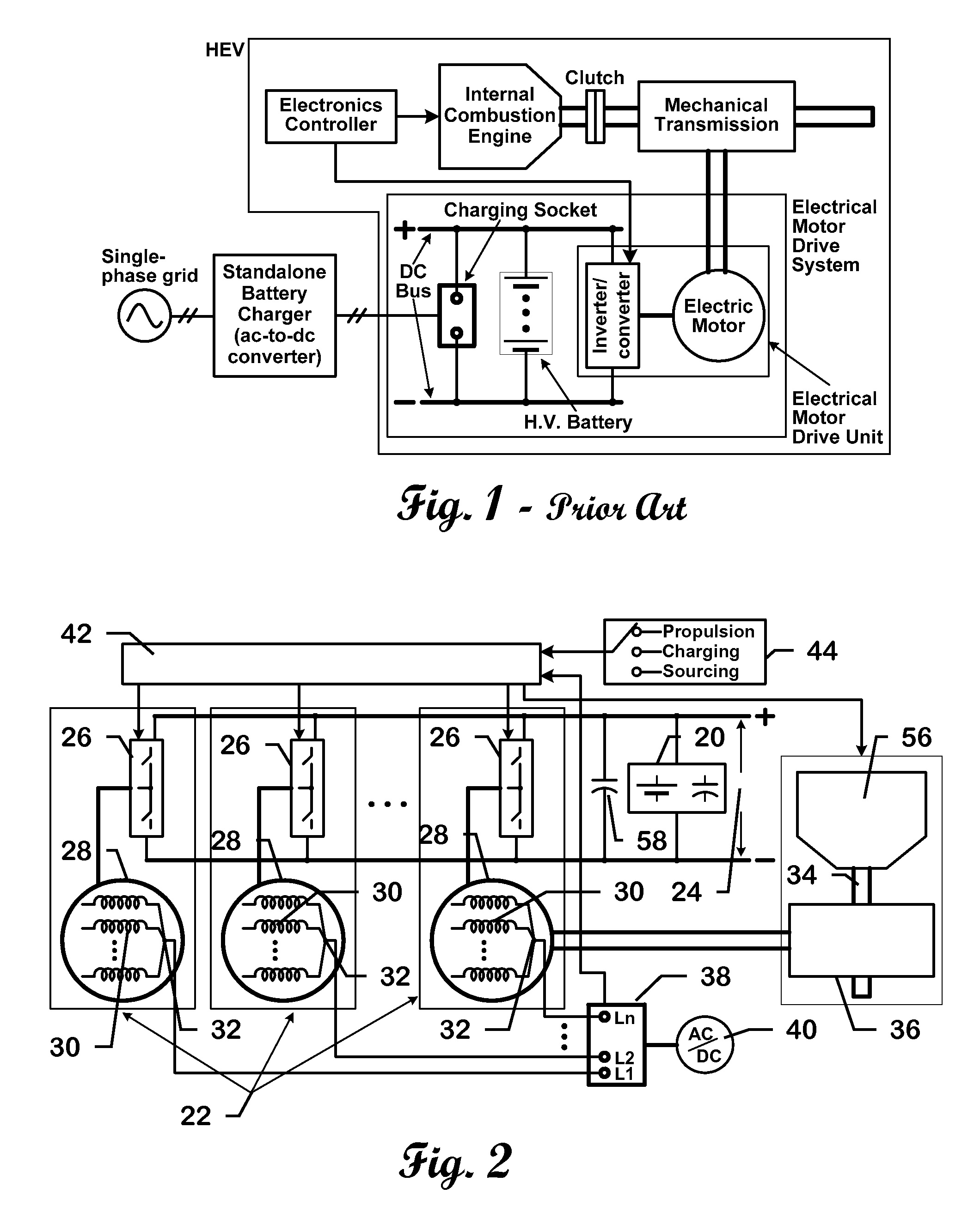
[0028]FIG. 2 shows an electrical drive system in HEVs. It is comprised of energy storage devices 20 such as batteries and ultra-capacitors, a filter capacitor 58, and multiple electrical motor drive units 22, all connected to a common dc bus 24. Each motor drive unit 22 employs an inverter / converter 26 (INV / CONV) and a multiphase motor / generator 28 (MG), whose stator windings 30 are bundled together at one end to from a neutral point 32 (NMG) while the other ends are connected to the inverter / converter 26. At least one drive unit 22 is coupled to the engine shaft 34 through a mechanical transmission device 36. The neutral points 22 of the motors / generators 28 are brought out to a phase number selection socket 38; each neutral point 32 is connected to a pin in the socket 38. The socket is used to selectively connect an external charging source 40 for charging the energy storage device 20, or external loads 40 for supplying power to the external loads 40, through some or all of the dr...

second embodiment

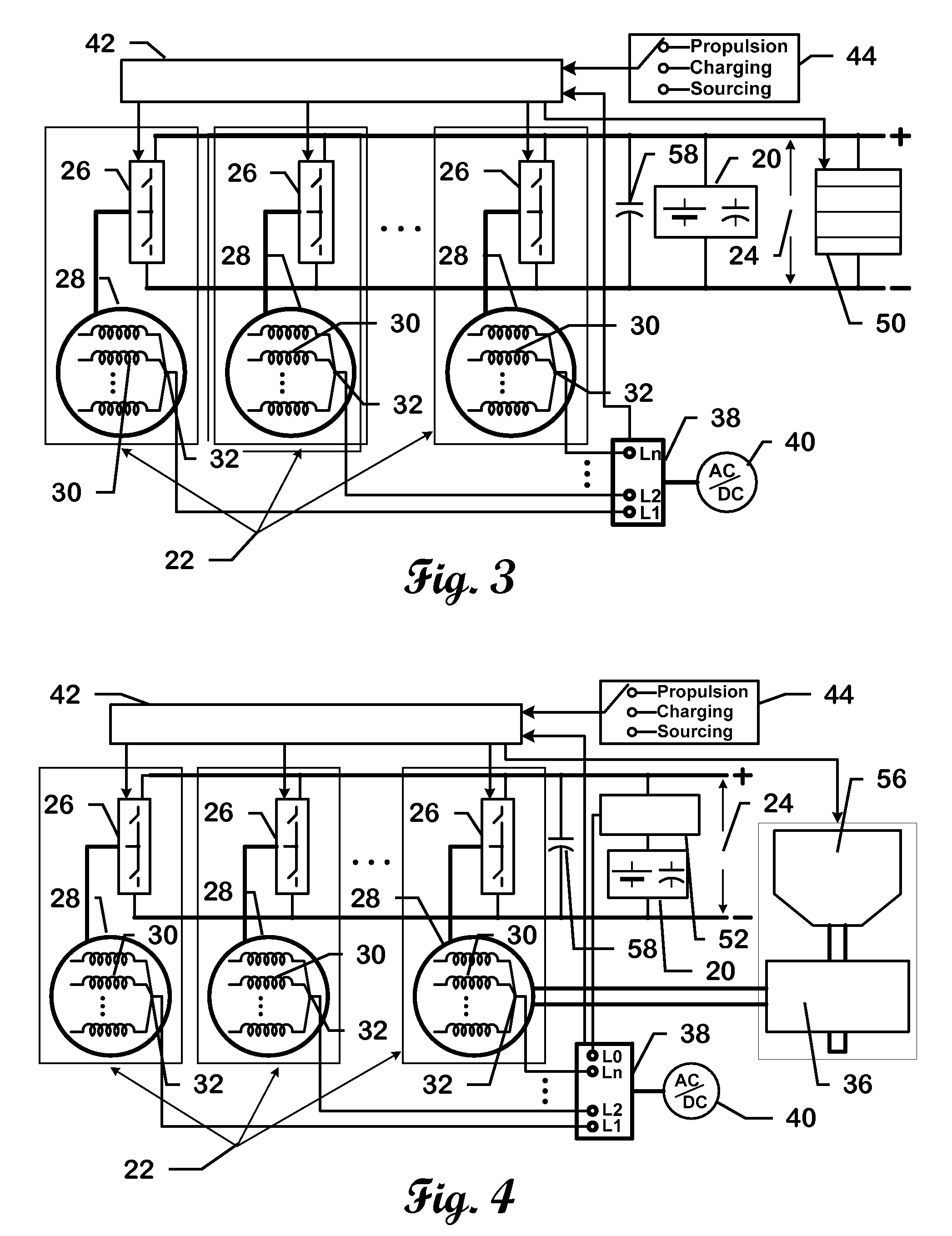
[0031]FIG. 3 shows an electrical drive system in fuel cell 50 powered vehicles.

[0032]FIGS. 4 and 5 show two embodiments that are constructed by adding of a bidirectional dc-to-dc converter 52 into FIGS. 2 and 3, respectively, for interfacing the storage device 20 to the dc bus 24. With the assistance of the dc-to-dc converter 52, the storage device 20 is decoupled from the dc bus 24 of high voltage and can operate at much lower voltage levels. Lower voltages batteries and ultra-capacitors are preferable because of higher reliability. The dc-to-dc converter also helps in maintain a fixed dc bus voltage desirable for controlling the motors / generators while extending the operating voltage range of the energy storage device.

[0033]FIG. 6(a) shows one preferred configuration of the first embodiment in FIG. 2 to provide four-wheel drive capability. It is comprised of a battery, and a dc bus filter capacitor (Cf) 58 and three electrical motor drive units, all connected to a common dc bus. E...

third embodiment

[0036]FIG. 8 shows one preferred configuration of the third embodiment in FIG. 4 to provide four-wheel drive capability and to use a lower voltage energy storage device. It is comprised of a battery, a contact switch 62, a dc-dc converter 52, a dc bus filter capacitor (Cf) 58, and three electrical motor drive units. The dc-dc converter 52 and the three electrical motor drive units are connected to a common dc bus. Each motor drive unit employs a three-phase inverter / converter 26 and a three-phase motor / generator (MG1, MG2 and MG3), whose stator windings are wired in a star connection. The neutral points of the motors / generators are brought out to a charging / sourcing socket 38. The external charging source can be a dc, or single-phase or three-phase ac power supply. Similarly, the external loads can be dc, single-phase or three-phase ac loads or the utility grids. The dc-dc converter is comprised of two switches 59 and 60 connected in series and an inductor 61 with one terminal conne...


PUM


Abstract

A power system that provides power between an energy storage device, an external charging-source/load, an onboard electrical power generator, and a vehicle drive shaft. The power system has at least one energy storage device electrically connected across a dc bus, at least one filter capacitor leg having at least one filter capacitor electrically connected across the dc bus, at least one power inverter/converter electrically connected across the dc bus, and at least one multiphase motor/generator having stator windings electrically connected at one end to form a neutral point and electrically connected on the other end to one of the power inverter/converters. A charging-sourcing selection socket is electrically connected to the neutral points and the external charging-source/load. At least one electronics controller is electrically connected to the charging-sourcing selection socket and at least one power inverter/converter. The switch legs in each of the inverter/converters selected by the charging-source/load socket collectively function as a single switch leg. The motor/generators function as an inductor.

Description

CROSS-REFERENCE TO RELATED APPLICATIONS [0001]This application claims priority from U.S. Provisional Patent Application 60 / 862,118 filed Oct. 19, 2006, herein incorporated by reference.STATEMENT REGARDING FEDERALLY SPONSORED RESEARCH [0002]This invention was made with United States Government support under Contract No. DE-AC05-00OR22725 between the United States Department of Energy and U.T. Battelle, LLC. The United States Government has certain rights in this invention.BACKGROUND OF THE INVENTION [0003]The use of electric vehicles (EVs) has been promoted in recent years to reduce oil consumption and the emissions of harmful pollutants and carbon dioxide. EVs may include battery powered vehicles, fuel cell powered vehicles, and hybrid electric vehicles (HEVs). Commercially available HEVs employ a battery and an electrical motor that are sized to optimize the energy efficiency of an internal combustion engine and to capture a portion of the kinetic energy for later use through dynam...

Claims


Application Information

Patent Timeline
IPC IPC(8): H02P1/26B60K8/00H02P1/00
CPCB60L11/1811B60L2210/20H02P5/747Y02T10/642Y02T10/7005Y02T10/725B60L2220/56Y02T90/14Y02T10/641B60L11/1812B60L11/1814B60L2220/54Y02T90/127Y02T10/7072B60L53/22B60L53/20B60L53/24Y02T10/64Y02T10/72Y02T10/70Y02T90/12
Inventor SU, GUI-JIA
Owner UT BATTELLE LLC
Why Eureka
Try Eureka