Movable body drive method and movable body drive system, pattern formation method and apparatus, exposure method and apparatus, and device manufacturing method

a technology of movable bodies and drive systems, applied in the direction of photomechanical devices, instruments, printing, etc., can solve the problems of inferior long-term stability of conventional encoders, lack of measurement value linearity of encoders, and inability to accurately measure the distance between the measurement value and the laser interferometer, etc., to achieve good precision and good precision

Inactive Publication Date: 2008-04-24
NIKON CORP
View PDF99 Cites 329 Cited by
  • Summary
  • Abstract
  • Description
  • Claims
  • Application Information

AI Technical Summary

Benefits of technology

[0015] According to this method, while the movable body is driven, positional information of the movable body in the movement plane is measured using at least two encoders of the encoder system, and the encoder used for position control of the movable body is switched from at least one of an encoder used for position control of the movable body to another encoder so as to maintain the position of the movable body in the movement plane before and after the switching. Therefore, although the switching of the encoder used for the control of the position of the movable body is performed, the position of the movable body in the movement plane is maintained before and after the switching, and a precise linkage becomes possible. Accordingly, it becomes possible to move the movable body two-dimensionally precisely along a predetermined course, while performing the linkage between a plurality of encoders.
[0066] According to the method, it becomes possible to drive the movable body two-dimensionally accurately at least within the predetermined plane, which in turn allows exposure of the object on the movable body to be performed with good precision.

Problems solved by technology

However, requirements for a stage position control with higher precision are increasing due to finer patterns that accompany higher integration of semiconductor devices, and now, short-term variation of measurement values due to temperature fluctuation of the atmosphere on the beam optical path of the laser interferometer has come to occupy a large percentage in the overlay budget.
Meanwhile, as a measurement unit besides the laser interferometer used for position measurement of the stage, an encoder can be used, however, because the encoder uses a scale, which lacks in mechanical long-term stability (drift of grating pitch, fixed position drift, thermal expansion and the like), it makes the encoder have a drawback of lacking measurement value linearity and being inferior in long-term stability when compared with the laser interferometer.
Further, the measurement resolution of the conventional encoder was inferior when compared with an interferometer, however, recently, an encoder which has a nearly equal or a better measurement resolution than a laser interferometer has appeared (for example, refer to Kokai (Japanese Patent Unexamined Application Publication) No. 2005-308592), and the technology to put the laser interferometer and the encoder described above together is beginning to gather attention.
However, as it can be easily imagined, for example, when considering the case when a grating is placed on the wafer stage, it is not so easy to perform linkage between a plurality of encoders while the wafer stage is being moved, especially while precisely the wafer stage is being moved two-dimensionally along a predetermined path.
Further, by repeating the linkage operation, the position error of the wafer stage may grow large with the elapse of time due to the accumulation of the error which occurs when linkage is performed, and the exposure accuracy (overlay accuracy) may consequently deteriorate.

Method used


Image

  • Movable body drive method and movable body drive system, pattern formation method and apparatus, exposure method and apparatus, and device manufacturing method
  • Movable body drive method and movable body drive system, pattern formation method and apparatus, exposure method and apparatus, and device manufacturing method
  • Movable body drive method and movable body drive system, pattern formation method and apparatus, exposure method and apparatus, and device manufacturing method

Examples


Embodiment Construction

[0111] Hereinafter, an embodiment of the present invention will be described, referring to FIGS. 1 to 40.

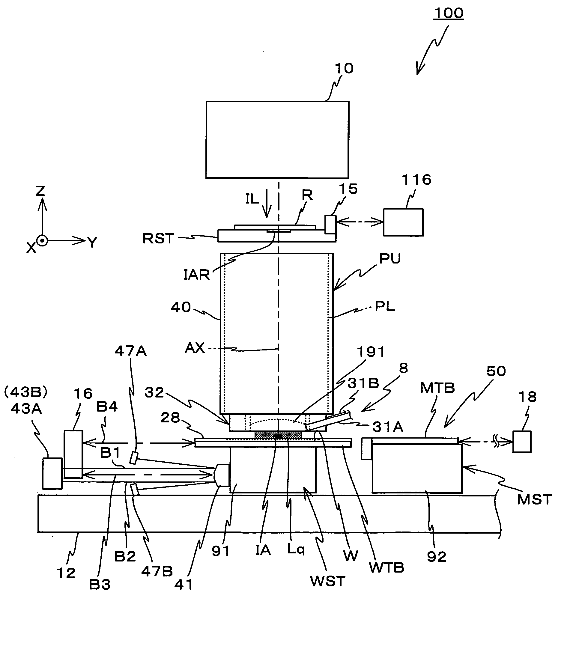
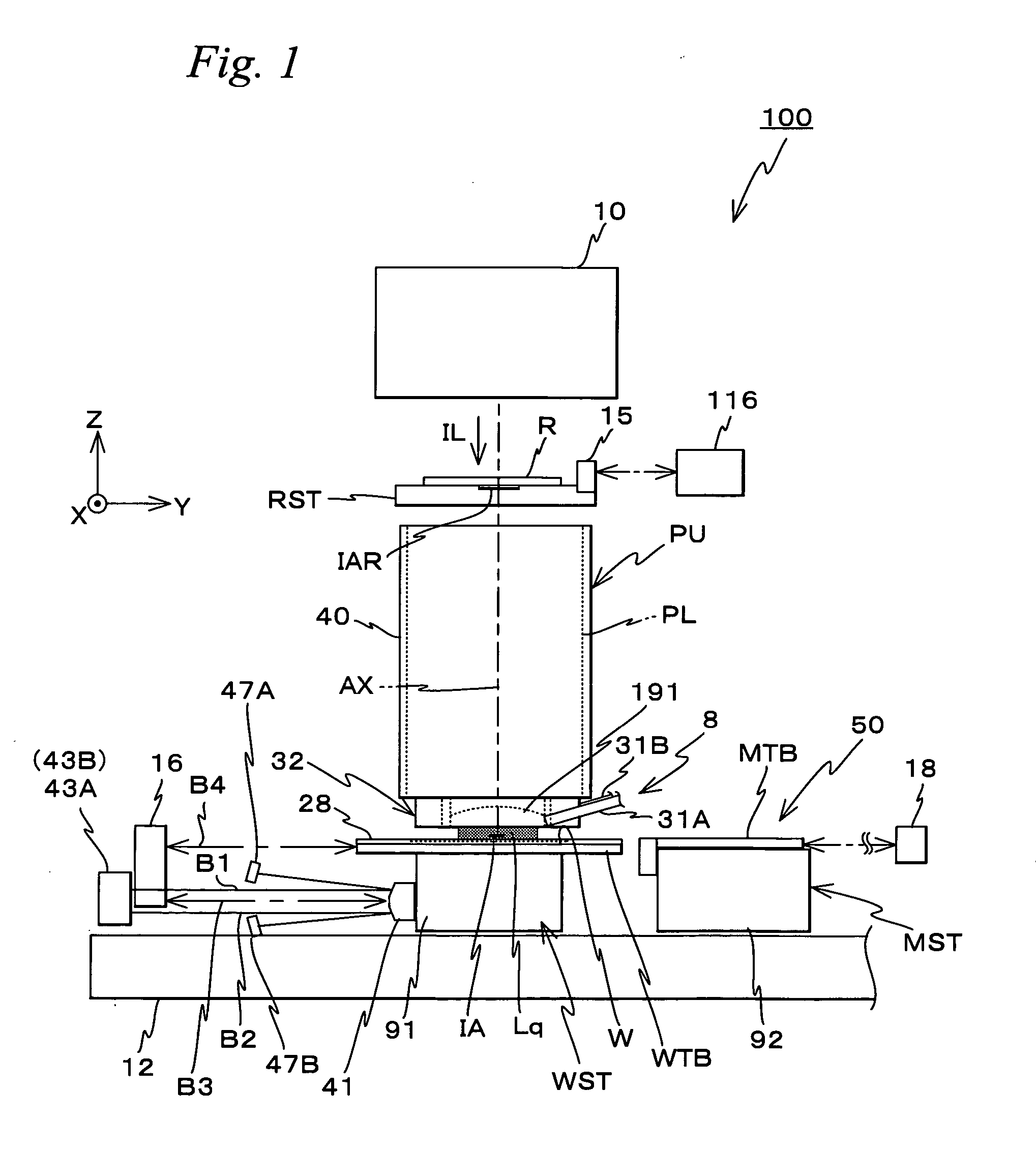
[0112]FIG. 1 shows a schematic configuration of an exposure apparatus 100 related to the embodiment.

[0113] Exposure apparatus 100 is a scanning exposure apparatus of the step-and-scan method, namely the so-called scanner. As it will be described later, a projection optical system PL is arranged in the embodiment, and in the description below, a direction parallel to an optical axis AX of projection optical system PL will be described as the Z-axis direction, a direction within a plane orthogonal to the Z-axis direction in which a reticle and a wafer are relatively scanned will be described as the Y-axis direction, a direction orthogonal to the Z-axis and the Y-axis will be described as the X-axis direction, and rotational (inclination) directions around the X-axis, the Y-axis, and the Z-axis will be described as θx, θy, and θz directions, respectively.

[0114] Exposure apparatus...


PUM


Abstract

During the drive of a stage, positional information in a movement plane of a stage is measured by three encoders that include at least one each of an X encoder and a Y encoder of an encoder system, and a controller switches an encoder used for a measurement of positional information of a stage in the movement plane from an encoder to an encoder so that the position of the stage in the movement plane is maintained before and after the switching. Therefore, although the switching of the encoder used for controlling the position of the stage is performed, the position of the stage in the movement plane is maintained before and after the switching, and a correct linkage becomes possible.

Description

BACKGROUND OF THE INVENTION [0001] 1. Field of the Invention [0002] The present invention relates to movable body drive methods and movable body drive systems, pattern formation methods and apparatuses, exposure methods and apparatuses, and device manufacturing methods, and more particularly to a movable body drive method in which a movable body is driven within a movement plane and a movable body drive system, a pattern formation method using the movable body drive method and a pattern formation apparatus equipped with the movable body drive system, an exposure method using the movable body drive method and an exposure apparatus equipped with the movable body drive system, and a device manufacturing method in which the pattern formation method is used. [0003] 2. Description of the Background Art [0004] Conventionally, in a lithography process for manufacturing microdevices (electron devices and the like) such as semiconductor devices and liquid crystal display devices, exposure app...

Claims


Application Information

Patent Timeline
Patent Type & Authority Applications(United States)
IPC IPC(8): G03B27/42G01B11/02G03B27/54H02K41/00
CPCG03F7/70725G03F7/70341G03F7/70775G03F9/7088G03F7/20G03F7/70141G03F7/70258G03F7/70616G03F7/70758G03F7/70783H01L21/0274G03F7/7085
Inventor SHIBAZAKI, YUICHI
Owner NIKON CORP
Why Eureka
Try Eureka