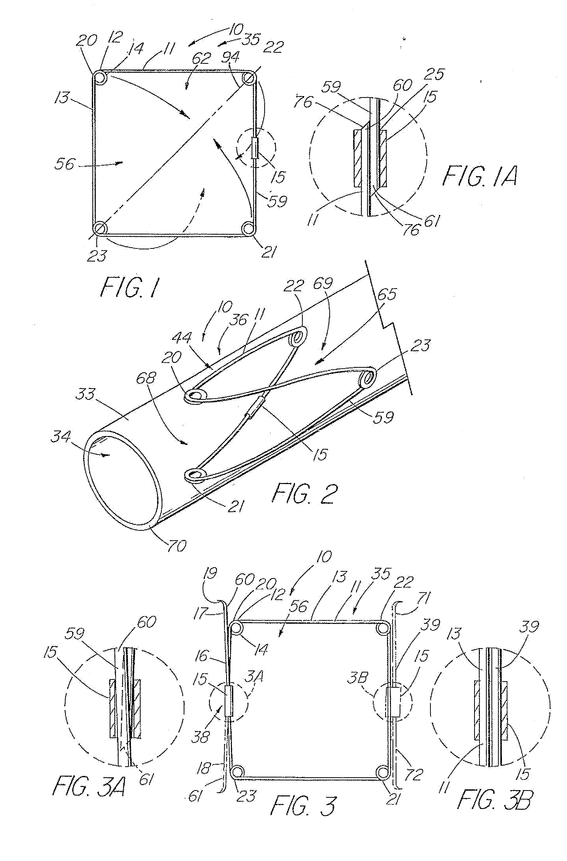
[0008] In another aspect of the invention, the valve includes a frame that is covered by a piece of
biocompatible material, preferably an
Extracellular Collagen Matrix (ECM) such as
small intestinal submucosa (SIS) or another type of submucosal-derived tissue. Other potential biomaterials include allographs such as harvested
native valve tissue. The material is slit or otherwise provided with an opening along one axis to form two triangular valve leaflets over a four-sided frame. In the deployed configuration, the leaflets are forced open by
normal blood flow and subsequently close together in the presence of
backflow to help eliminate
reflux. Other configurations include a two-leaflet valve having an oval or elliptically shaped frame, and valves having three or more legs and associated leaflets, which provide a better distribution of the load exerted by the column of fluid acting on the leaflets.
[0011] A second series of embodiments include centering support structure, such as a plurality of lateral elements or arms and / or supplemental legs, that extends laterally from the valve portion to provide additional contact points along the circumference of the vessel for longitudinal support, contact points being generally defined as the bends which typically supply concentrated radial force against the vessel wall (as opposed to the struts that although in contact the vessel wall, typically supply less radial force). Additionally, the lateral elements, which are preferably positioned behind the leaflets and interposed between the leaflet and vessel wall, can offer protection to the leaflets so that they are at least partially blocked and generally unable to adhere to the vessel wall, which can collapse onto the leaflets due to how the valve radially expands and conforms to the vessel. The lateral elements or arms can comprise separate components attached to the basic valve portion frame, or the frame itself can comprise multiple elements or subassemblies that can be assembled to form a closed valve portion frame with two laterally extending arms. Each lateral arm can include one contact point or additional contact points for added stability.
[0012] In another embodiment, the centering support structure comprises two lateral arms, which protect the two leaflets and provide longitudinal support, and two supplemental legs about the distal end of the valve portion for further stabilization to prevent tilting. One method of forming the frame includes attaching two zig-zag or serpentine-shaped stents end to end, with struts, sutures, or another well-known mechanism. Each zig-zag
stent comprises a four or more serpentine sections with at least two opposite sections comprising either lateral arms (proximal
stent) or supplemental legs (distal stent), with the other two serpentine sections on each stent comprising a half of one of the valve section legs. Strut lengths, wire diameters, eye diameters, and angles and widths of serpentine sections can be varied to produce optimum
radial pressure that the device exerts on the vessel wall, depending on the size of the valve and
vessel diameter. The optimal
radial pressure is one at which the valve conforms to the vessel and prevents
reflux without causing
erosion or damage to the vessel wall that could lead to rupture.
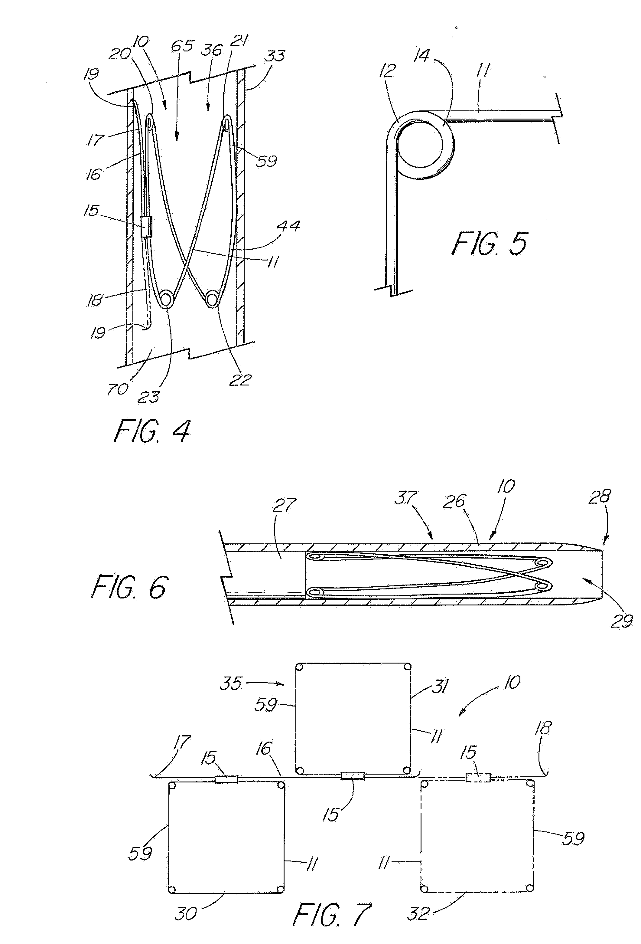
[0013] In the double serpentine stent embodiment, the covering comprising the leaflets is attached to the frame so that each leaflet spans the two stents or serpentine row section with a lateral arm extending outward so that it is external to the leaflet and frame. In an embodiment in which the serpentine stents are attached using a long strut that also adds rigidity to the valve legs which helps prevent partial collapse due to the weight of the blood column, the ends of the struts extend beyond the bends of the valve portion frame to serve as barbs. To help prevent entanglement with the barbs during loading of the device with the
delivery system, and modifying
radial pressure, the adjacent lateral arms and supplemental legs can be made shorter or longer than the adjacent serpentine sections that comprise the valve legs, so that their respective contact points are offset relative to the ends of the barbs. Additionally, the struts of the serpentine sections can be curved to produce a more rounded configuration for improved conformity with the vessel. The frame can also be
laser cut or otherwise formed from nitinol tubing, or some other material, to create multiple serpentine row sections (e.g., at least 2-4) interconnected by struts with the leaflets spanning multiple rows.
[0014] In another embodiment of the present invention, the valve portion is attached inside an expandable stent, or a sleeve of material, such as SIS, that is configured to provide longitudinal stability and prevent tilting. The sleeve can further include an anchoring stent about one end that is deployed ahead of, or after, the valve portion to prevent tilting of the valve.
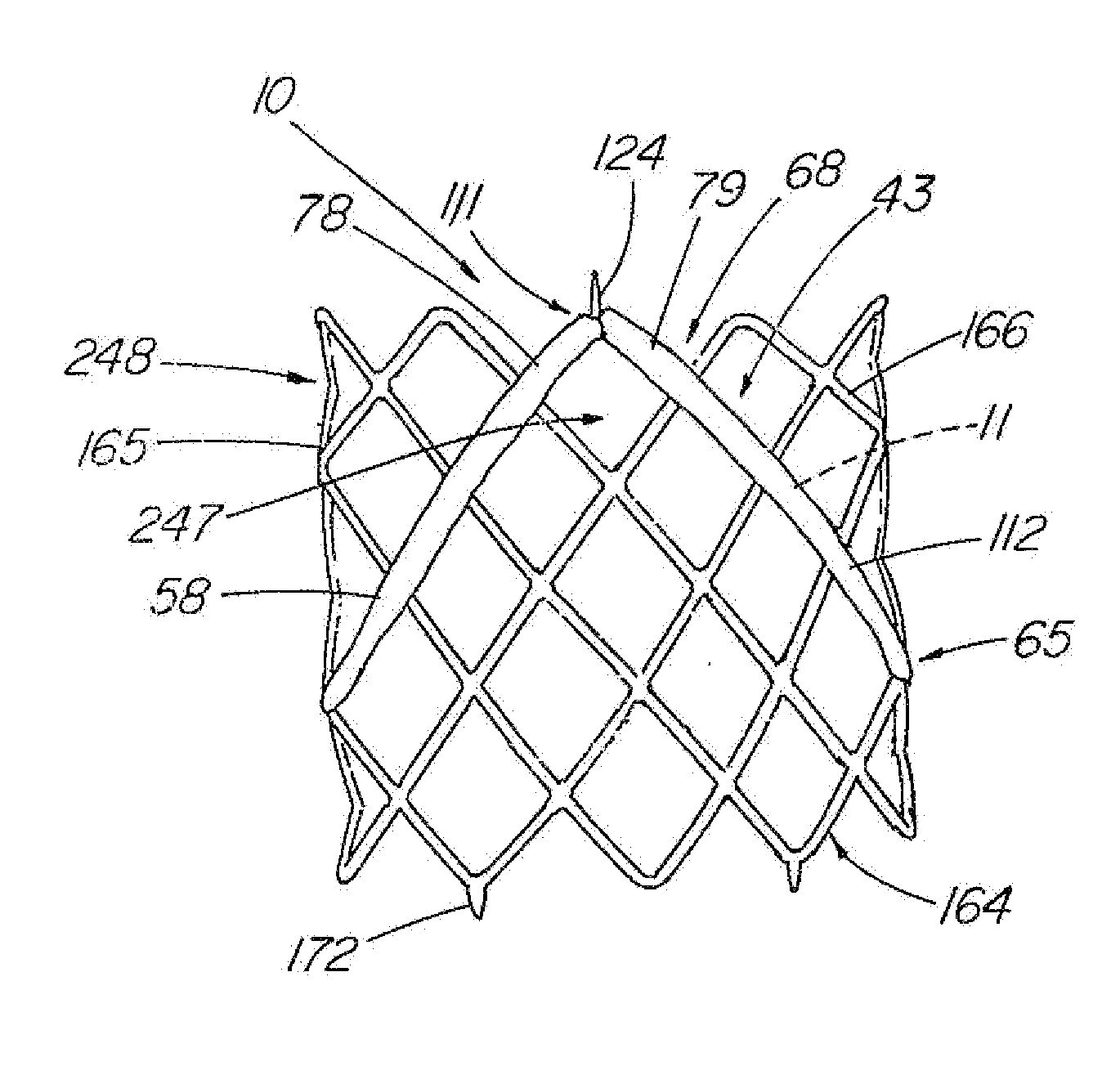
[0015] In still another aspect of the present invention, the frame of the device is modified by placing one or more of the bends under tension which results in the frame assuming a second shape that has superior characteristics of placement within the vessel. One method of adjusting the shape includes forming the bends in the wire at an initial angle, e.g., 150°, that is larger than the desired final angle, e.g., 90° for a four-sided valve, so when the frame is constrained into the final configuration, the sides are arcuate and bow outward slightly. The curvature of the sides allows the sides to better conform to the rounded contours of the vessel wall when the valve is deployed. In devices having a full or partial covering of material over the frame, a second method of modifying the shape is to use the material to constrain the frame in one axis. One such embodiment includes a four-sided valve with two triangular-shaped halves of material, such as SIS, where the material constrains the frame in
a diamond shape. This puts the bend of the frame under stress or tension which permits better positioning within the vessel. It also allows the
diagonal axis of the frame with the slit or orifice to be adjusted to the optimal length to properly size the frame for the vessel such that the leaflets open to allow sufficient flow, but do not open to such a degree that they contact the vessel wall. The potential benefits of both adding tension to the bends to bow the sides and constraining the frame into
a diamond shape using the covering, can be combined in a single embodiment or employed separately.

