Diagnosis and calibration system for ICP-MS apparatus

a calibration system and analyzer technology, applied in the direction of instruments, separation processes, nuclear elements, etc., can solve the problems of inability to analyze, and inability to perform dilution by hand, etc., to achieve easy confirmation of device properties, short time, and improve reproducibility.

Active Publication Date: 2008-05-01
AGILENT TECH INC
View PDF3 Cites 8 Cited by
  • Summary
  • Abstract
  • Description
  • Claims
  • Application Information

AI Technical Summary

Benefits of technology

[0026]By means of the diagnosis and calibration system of the present disclosure, an on-site user of the above-mentioned ICP-MS can confirm whether or not the standard properties of a device are stable, and reproducibility can be improved when samples of various matrix

Problems solved by technology

When a high-matrix sample is analyzed by conventional methods using conventional devices, there are problems in that, as a result of large numbers of ions being guided to the tail of the device, oxides and the like are deposited and pollute the surfaces of the sampling cone, skimmer cone, etc., and the orifices become clogged, making analysis impossible.
Performing dilution by hand takes time.
Diluting many samples is particularly an inconvenience in terms of time, and there is also the chance that there will be errors in dilution.
Nevertheless, there is the chance that the sample will be contaminated by the outside environment or the tools that are used during dilution of the liquid sample.
The first problem with this method is that the measurement results tend to fluctuate because, in

Method used


Image

  • Diagnosis and calibration system for ICP-MS apparatus
  • Diagnosis and calibration system for ICP-MS apparatus
  • Diagnosis and calibration system for ICP-MS apparatus

Examples


Embodiment Construction

[0035]The diagnosis and calibration system for an ICP-MS that is a preferred embodiment of the present disclosure will now be described while referring to the attached drawings. First, the general structure of the ICP-MS will be shown and the diagnosis and calibration system will then be described. It should be noted that the term “dilution” used in the description of the mode of operation of the present disclosure that follows includes all means with which it is possible to reduce the amount of sample ions that pass through the interface part, and in places other than the description of prior art, it also refers to so-called “dry” dilution by which a liquid is not used.

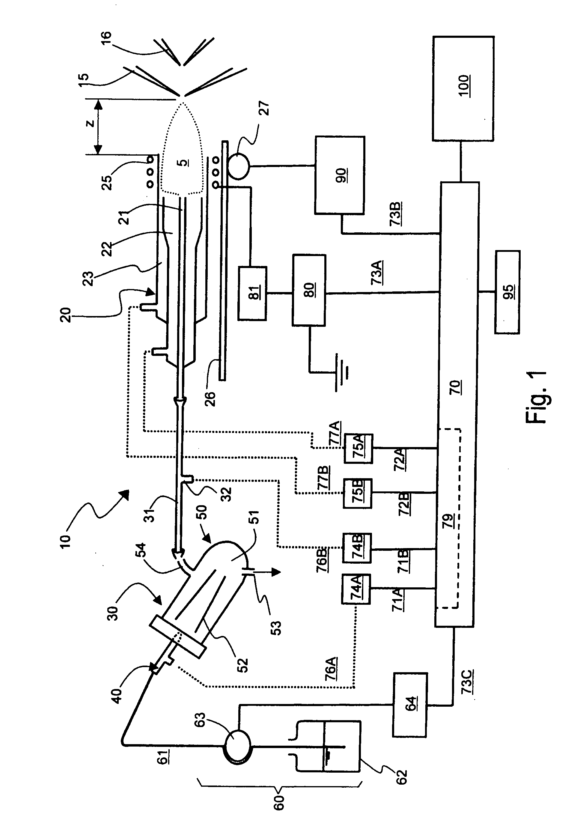
[0036]FIG. 1 shows primarily the plasma-generating part of the main section of the ICP-MS of the present disclosure. This type of ICP-MS comprises a mass spectrometer part at the back of the plasma generating part. FIG. 1 shows only a sampling cone 15 and a skimmer cone 16, which are at the front of the mass-analyzin...


PUM


Abstract

A diagnostic system designed such that an aggregate of parameter combinations is stored, which is an aggregate of combinations of parameters consisting of a first parameter for determining the output of the high-frequency power source, a second parameter for determining the flow rate of the carrier gas in the aerosol, and a third parameter for determining the distance between the plasma torch and the interface, and which forms a specific array such that the measurement points corresponding to the respective combinations are lined up in order along the direction of length of an envelope that forms the end on the high-sensitivity side of a graph drawn as an aggregate of all measurement points on a sensitivity-oxide ion ratio graph, and a diagnostic measurement is performed with a specific diagnostic sample using the parameter value of each combination of the above-mentioned parameter combinations that form the aggregate such that the device properties can be confirmed from the position on the envelope on the sensitivity-oxide ion ratio graph of the actual measurement points corresponding to each combination.

Description

BACKGROUND[0001]1. Field of the Disclosure[0002]The present disclosure relates to a diagnostic system and calibration system for analyzer devices, and in particular, to a system for the diagnosis and correction of device properties of an inductively coupled plasma mass spectrometer (ICP-MS).[0003]2. Discussion of the Background Art[0004]The ICP-MS is known as a high-sensitivity analyzer for detecting traces of metal ions. By means of this analyzer, a sample to be measured is introduced inside the plasma and the sample to be measured becomes ions, these ions are extracted, and mass analysis is performed, and the basic structure of this spectrometer comprises a plasma-generating part for generating plasma from a sample such as a liquid, and a mass-analyzing part for extracting ions from the generated plasma and analyzing these ions.[0005]The plasma-generating part, particularly in the case of a liquid sample, comprises a nebulizer for nebulizing a liquid sample using a gas having a sp...

Claims


Application Information

Patent Timeline
IPC IPC(8): G01D18/00
CPCH05H1/30
Inventor SAKATA, KENICHISHIBUKAWA, TATSUYA
Owner AGILENT TECH INC
Why Eureka
Try Eureka