Eureka AIR delivers breakthrough ideas for toughest innovation challenges, trusted by R&D personnel around the world.

Erosion resistant coatings and methods of making

a technology of erosion resistance and coating, applied in the direction of superimposed coating process, machine/engine, natural mineral layered products, etc., can solve the problems of frequent maintenance related shutdown of turbine components, lack of erosion or corrosion resistance of martenitic stainless steel,

Inactive Publication Date: 2008-05-01
GENERAL ELECTRIC CO
View PDF2 Cites 37 Cited by
  • Summary
  • Abstract
  • Description
  • Claims
  • Application Information

AI Technical Summary

Benefits of technology

"The patent describes a coated turbine engine component that includes a coating made of erosion-resistant materials applied using electron beam physical vapor deposition or ion plasma cathodic arc deposition. The coating can be a single layer or a multilayer, with a roughness average of less than or equal to about 75 microinches. The technical effect of the coating is to provide better protection against erosion and wear caused by high temperatures and corrosive environments in which the turbine engine component operates."

Problems solved by technology

Existing base materials for turbine components such as, but not limited to, martensitic stainless steels do not have adequate erosion or corrosion resistance under these conditions.
The severe erosion that can result may damage the turbine components, thereby contributing to frequent maintenance related shutdowns, loss of operating efficiencies, and the need to replace various components on a regular basis.
These processes produce as-deposited coatings with rough surface textures and limited hardness, which can have adverse affects on the performance of the turbine.
In addition, these processes can produce coatings that can adversely affect the high cycle fatigue strength of the substrate or base material.
Finally, the coatings produced by these processes often require modification to the turbine airfoil to compensate for the thickness of the coatings.
Unfortunately, these are expensive and time consuming processes.
Consequently, many applications forego this type of machining or polishing.

Method used


Image

  • Erosion resistant coatings and methods of making
  • Erosion resistant coatings and methods of making
  • Erosion resistant coatings and methods of making

Examples


Embodiment Construction

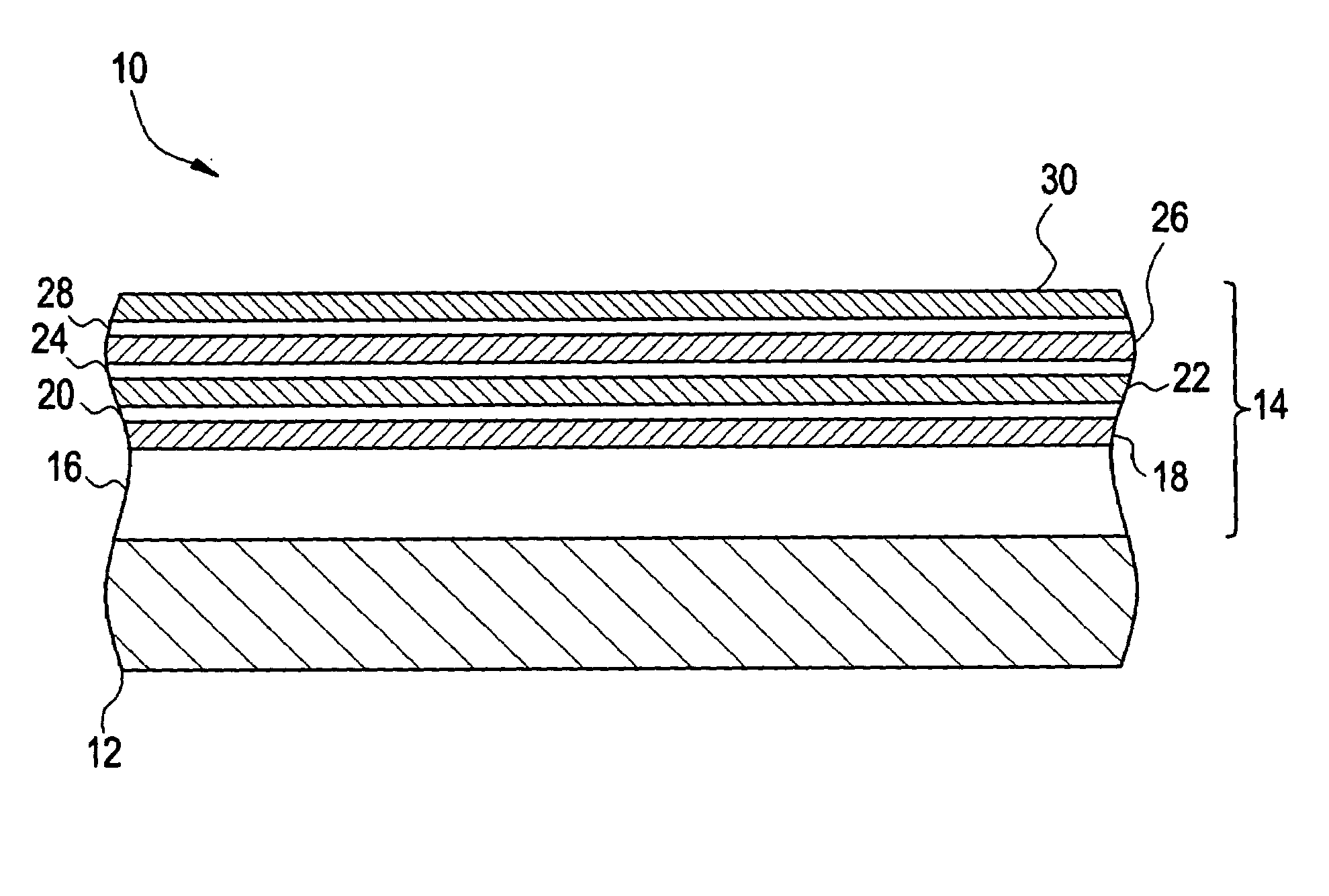
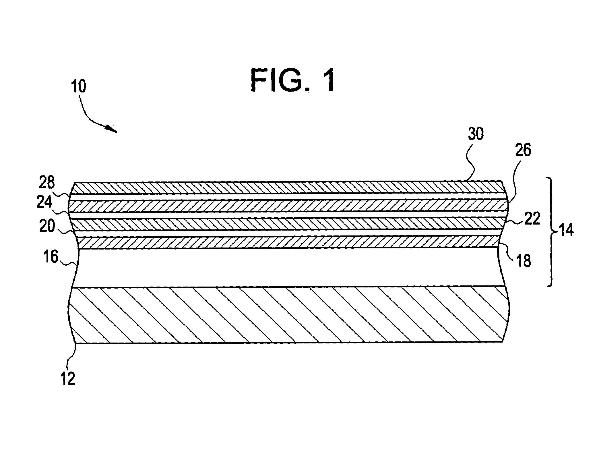
[0015]Coating compositions and coating methods that provide erosion resistance to metal turbine engine components are disclosed herein. The methods are generally based on the electron beam-physical vapor deposition (EB-PVD) or ion plasma cathodic arc deposition of a coating on a smooth turbine engine component substrate. The methods result in coatings with decreased surface roughness relative to existing coatings. Advantageously, the as-deposited coatings do not require a post-deposition machining or polishing step to achieve the decreased surface roughness. Furthermore, the coatings provide increased dimensional stability to the coated surface during operation of the turbine. For example, the coated turbine engine component has a high cycle fatigue (HCF) strength that is greater than or equal to that of the turbine engine component without the erosion resistant coating disposed thereon. Accordingly, adverse effects, such as decreased turbine efficiency and power output, which are o...


PUM

PropertyMeasurementUnit
thicknessaaaaaaaaaa
total thicknessaaaaaaaaaa
thicknessaaaaaaaaaa

Abstract

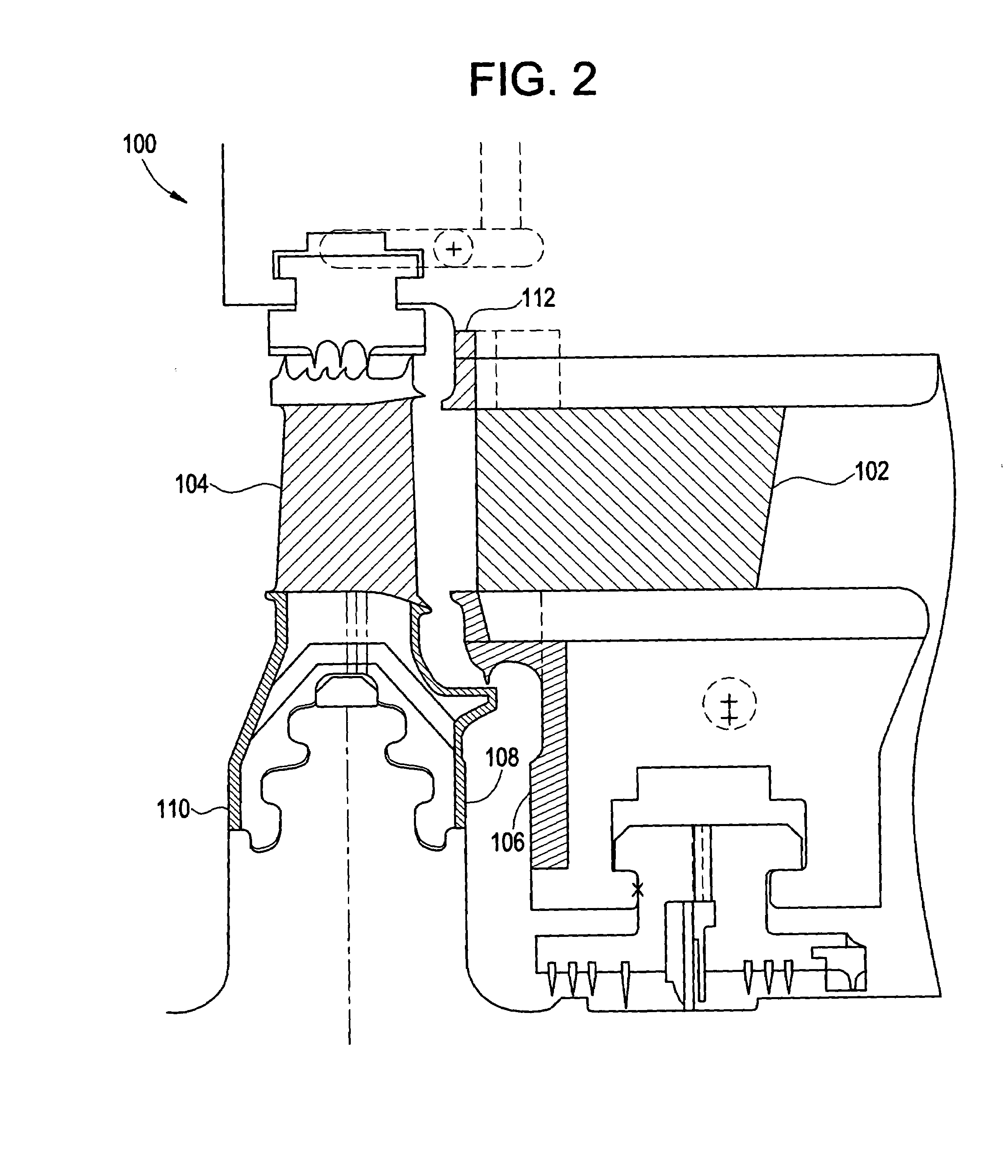
A coated turbine engine component includes a turbine engine component and an erosion resistant coating disposed on at least a portion of a surface of the turbine engine component using electron beam physical vapor deposition or ion plasma cathodic arc deposition.

Description

BACKGROUND OF THE INVENTION[0001]The present disclosure relates to coating compositions and coating methods, and more particularly to erosion resistant coating compositions and coating methods.[0002]Metal components are used in a wide variety of industrial applications, under a diverse set of operating conditions. In many cases, the components are provided with coatings, which impart various characteristics, such as corrosion resistance, heat resistance, oxidation resistance, and erosion resistance. As an example, erosion-resistant coatings are frequently used on the first stages of high pressure and intermediate pressure steam turbines that are particularly prone to solid particle erosion. In addition, erosion-resistant coatings are frequently used on compressor sections of gas turbines and jet engines that are prone to sand or other airborne solid particle erosion as well as corrosion.[0003]Erosion of these components generally occurs by impingement of solid particles (e.g., sand ...

Claims


Application Information

Patent Timeline
Patent Type & Authority Applications(United States)
IPC IPC(8): C23C16/00B32B15/04B32B9/00H01T14/00B32B19/00
CPCC23C14/0641C23C28/42C23C14/30F01D5/286F01D5/288Y02T50/67Y02T50/672Y02T50/673F05D2260/95F05D2250/60F05D2230/31F05D2230/313C23C28/322C23C28/347C23C14/18Y02T50/60C23C14/00C23C28/00
Inventor GHASRIPOOR, FARSHADTURNQUIST, NORMAN ARNOLDVARANASI, KRIPA KIRANCORDERMAN, REED ROEDERFEENY, SEAN DOUGLAS
Owner GENERAL ELECTRIC CO
Why Eureka
Eureka Blog
Learn More