Linear Motor System

Inactive Publication Date: 2008-05-08
YASKAWA DENKI KK
View PDF7 Cites 31 Cited by
  • Summary
  • Abstract
  • Description
  • Claims
  • Application Information

AI Technical Summary

Benefits of technology

[0075]According to the invention cited in claim 1, the semiconductor switch that constitutes the winding switching device is open or closed, and when it is closed, a winding group connected to the winding switching device is set to a state wherein it is connected as a star connection to the controller. Thus, as the controller supplies a current, the current flows to the winding group, so that the winding group is excited. Further, when the semiconductor switch is open, the neutral point side of the star connection is in the open state, and even when a current is supplied by the controller, the current does not flow through the winding group, so that the winding group can not be excited. Therefore, by opening or closing the semiconductor switch of the winding switch device that is connected to one of a plurality of winding groups separated in the direction of thrust, only a desired winding group can be excited. The thrust is generated at the winding group of the stator that is opposite the permanent magnet provided for the stator.
[0076]Since this linear motor system can excite only a desired winding group, the system can reduce loss to merely the loss that is generated in a winding group where a thrust is generated when the stroke is extended. Thus, a saving in energy can be realized.
[0077]Furthermore, the controller requires only the capacity to supply a generated thrust and the only loss is caused by the winding group

Problems solved by technology

The controller 904 is generally expensive, and a problem exists with costs when the controller 904 is employed to extend a stroke.
The

Method used


Image

  • Linear Motor System
  • Linear Motor System
  • Linear Motor System

Examples


embodiment 1

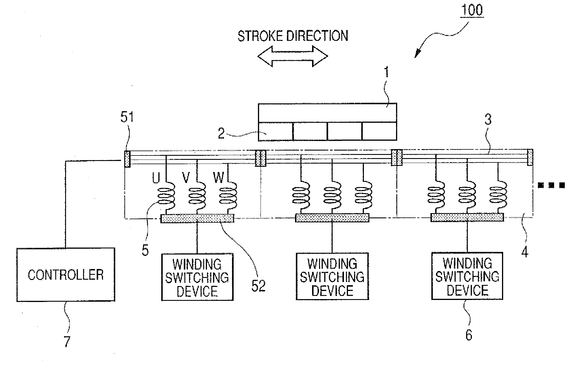
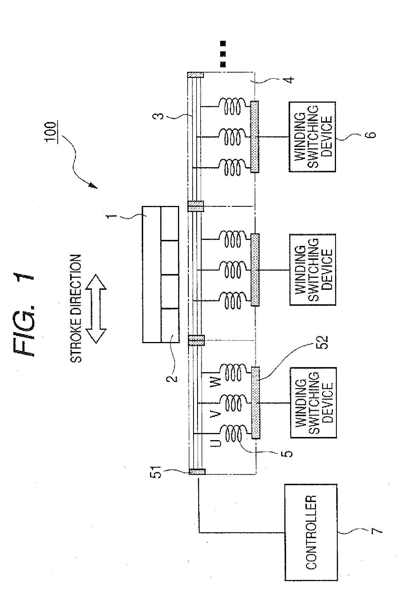
[0154]FIG. 1 is a configuration diagram of a linear motor system showing a first embodiment of the present invention.

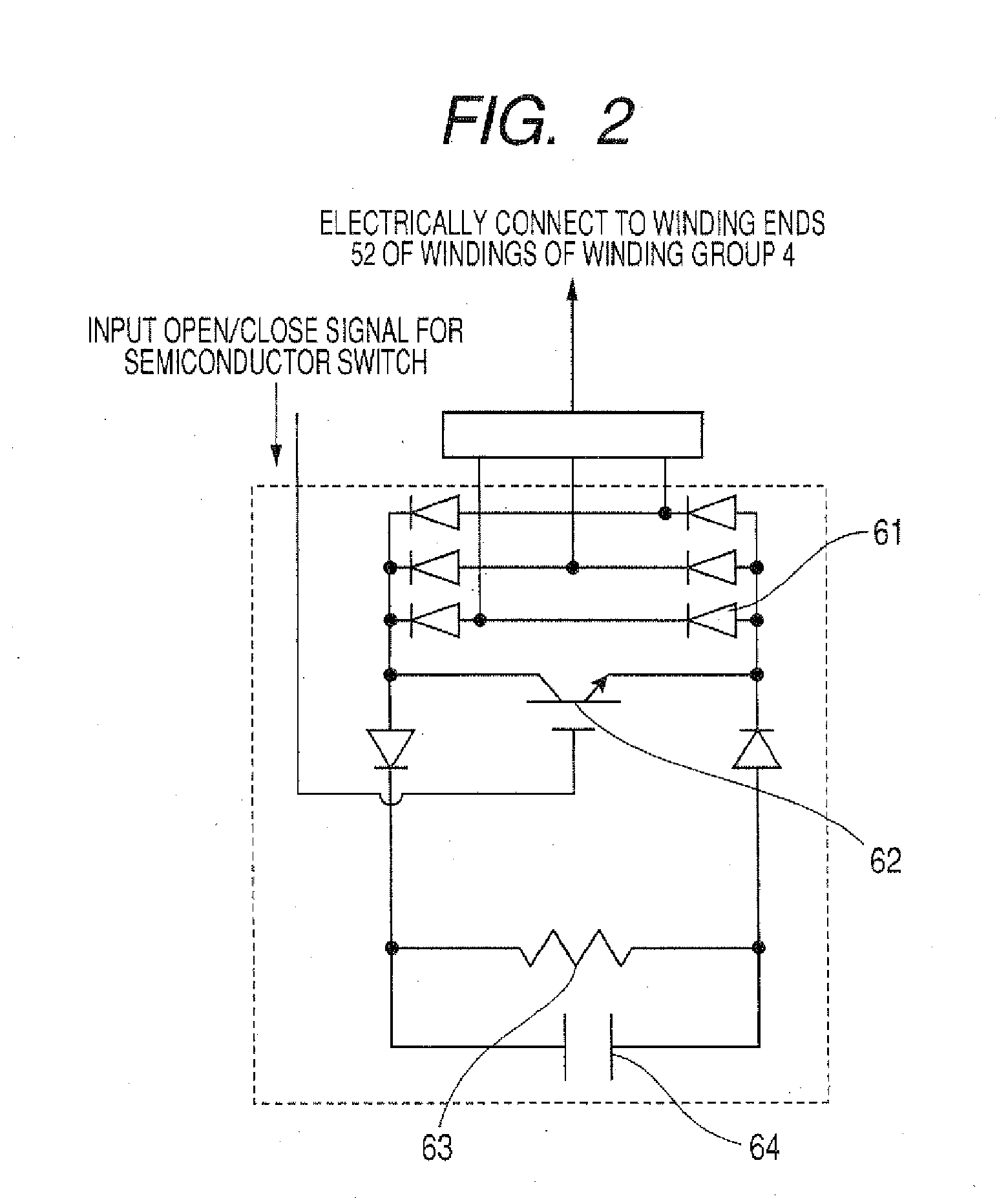
[0155]FIG. 2 is a diagram for explaining the configuration of a winding switching device in FIG. 1.

[0156]In FIG. 1, reference numeral 100 denotes a linear motor; 1, a moving element; 2, a permanent magnet; 3, a stator; 4, winding groups; 5, windings; 6, winding switching devices; and 7, a controller.

[0157]The moving element 1 is constituted by the adherence of the permanent magnets 2, in the stroke direction, so that their adjacent polarities differ. The stator 3 is constituted by arranging, in the stroke direction, a plurality of the winding groups 4, each formed of the windings 5 that have a U phase, a V phase and a W phase. The moving element 1 and the stator 3 are coupled together by a guide (not shown), and the moving element 1 can move freely, relative to the stator 3, in the stroke direction. For the windings 5 of the U phase, V phase and the W phase that form ...

embodiment 2

[0168]FIG. 3 shows a second embodiment of the present invention.

[0169]In FIG. 3, reference numeral 8 denotes a sensor for detecting whether a moving element is positioned opposite.

[0170]For individual winding groups 4 that constitute a stator 3, the sensor 8 for detecting that a moving element 1 is opposite a winding group 4 is arranged on the faces directed toward the moving element 1. The output terminals of the sensors 8 are connected to the signal terminals, for opening and closing semiconductor switches 62, of winding switching devices 6 that are connected to the winding groups 4 where the sensors 8 are provided.

[0171]When a sensor 8 detects it is opposite the moving element 1, the sensor 8 transmits a close signal to the connected semiconductor switch 62. Upon receiving this signal, the semiconductor switch 62 is closed, and windings 5 of a winding group 4 that is connected to the winding switching device 6, where the semiconductor switch 62 is arranged, are excited by receivi...

embodiment 3

[0174]FIG. 4 shows a third embodiment of the present invention.

[0175]In FIG. 4, for a length Lml of a moving element 1 in the stroke direction and a length Lc, in the stroke direction, of a winding group 4 that constitutes a stator 3, the length relationship

Lml=n×Lc [0176]n: an integer of 2 or greater

is established. In this embodiment, n is 2, and the length Lc of the winding group 4 is defined as half the length Lml of the moving element 1 in the stroke direction.

[0177]On the face of each winding group 4 opposite the moving element 1, two sensors, 81 and 82, for detecting that the moving element 1 is opposite the winding group 4, are mounted at respective ends in the stroke direction. A signal processing circuit 9 is provided between the sensors 81 and 82 and a winding switch device 6 that receives signals from the sensors 81 and 82, so that, when both of the sensors 81 and 82, mounted at both ends in the stroke direction, detect that the moving element 1 is opposite, the sensors 8...


PUM


Abstract

A linear motor system that can extend the stroke of a linear motor, with power saving and at a low cost, is provided.
In a linear motor system, constituted by a linear motor 100, a controller 7 for supplying a variable voltage, a winding switching device 6, for opening and closing phase windings 5 of individual phases that form a plurality of winding groups 4 that are separated in a stroke direction, the winding switching device 6 is constituted by a three-phase rectifying member, a semiconductor switch, which is located at both ends on the direct-current output side of the three-phase rectifying member, and a resistor and a capacitor, connected in parallel to the semiconductor switch. For each of the phase windings, which form the plurality of winding groups 4, separated in the stroke direction, one end is connected to the output end of the controller 7 and the other end is connected to an alternating-current input side of the three-phase rectifying member of the winding switching device 6. And by opening or closing the semiconductor switch included in the winding switching device 6, of the plurality of winding groups 4 separated in the stroke direction, only a desired winding group 4 is excited.

Description

TECHNICAL FIELD[0001]The present invention relates to a linear motor system that extends the stroke of a linear motor, with energy savings and at a low cost, and relates in particular to a long-stroke linear motor system that includes a winding switching device therefor.[0002]Further, the present invention relates to a fixed armature type linear motor wherein the stator side is formed of a linear motor stator and an armature winding, and the moving element side is formed of a set of permanent magnets and a secondary conductor.BACKGROUND ART[0003]A conventional linear motor system includes, as a moving element, permanent magnets that serve as magnetism loading means; and as a stator, windings that serve as electricity loading means. A plurality of windings are arranged in a stroke direction, and controllers are respectively provided for supplying a current to the windings and are connected to an interval switching device (see, for example, patent document 1).[0004]The conventional li...

Claims


Application Information

Patent Timeline
IPC IPC(8): H02K41/02H02P7/28H02K41/03H02P25/06
CPCB60L13/03H02K11/0021H02K41/031H02K16/04H02P25/06H02K3/28H02K2213/12H02K11/215H02P6/006H02P25/064
Inventor YAMADA, KENJIMAEMURA, AKIHIKOMORIMOTO, SHINYASHIKAYAMA, TORUTANAKA, YOSHIYUKITAKAKI, MAMORU
Owner YASKAWA DENKI KK
Why Eureka
Try Eureka