Compact structure of starter

a compact, starter technology, applied in the direction of engine starters, electric generator control, machines/engines, etc., can solve the problems of failure of pinion engagement, increase in mechanical wear of the end of the shift lever b>, and decrease in amount, so as to reduce the mass or weight, the effect of reducing the siz

Active Publication Date: 2008-05-08
DENSO CORP
View PDF14 Cites 9 Cited by
  • Summary
  • Abstract
  • Description
  • Claims
  • Application Information

AI Technical Summary

Benefits of technology

[0012]Specifically, the holder is lower in mass or weight than the pinion, thereby permitting the magnetic attraction, as produced by the electromagnetic actuator, required to shift the pinion carrier toward the ring gear through the shift lever to be decreased. This permits the electromagnetic actuator to be decreased in size.

Problems solved by technology

Therefore, in the case where the shift lever 160 is made of resin for saving the weight and production cost thereof, it will result in an increase in mechanical wear of the end of the shift lever 160 resulting from the friction with the rotating surface 131 of the spline tube 130.
This results in a decrease in amount by which the shift lever 160 moves the pinion 140 toward the engine, which may lead to a failure in engagement of the pinion 140 with the ring gear 170.

Method used


Image

  • Compact structure of starter
  • Compact structure of starter
  • Compact structure of starter

Examples


first embodiment

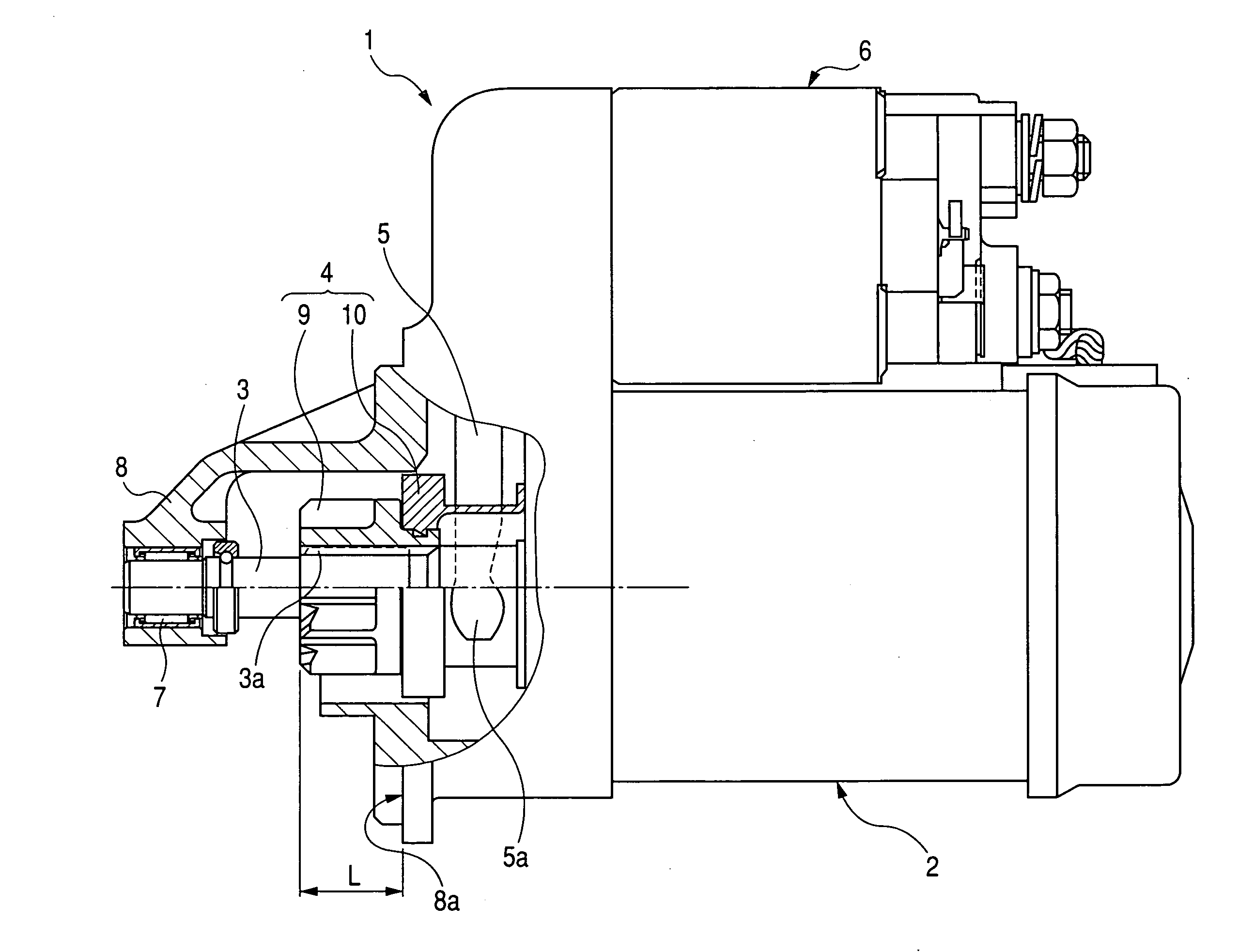
[0026]Referring to the drawings, wherein like reference numbers refer to like parts in several views, particularly to FIG. 1, there is shown a starter 1 according to the invention which may be employed in starting an automotive internal combustion engine.

[0027]The starter 1 consists essentially of an electric motor 2, an output shaft 3, a pinion carrier 4, and an electromagnetic switch 6. The motor 2 works to produce torque which is, in turn, transmitted to the output shaft 3 through a clutch (not shown). The pinion carrier 4 is, as will be described later in detail, installed on the output shaft 3. When turned on, the electromagnetic switch 6 works as an actuator to push or shift the pinion carrier 4 to the side of an engine (i.e., a left direction, as viewed in the drawing) through a shift lever 5 and at the same time closes contacts of a main switch installed in a motor circuit for the motor 2.

[0028]When the main switch is closed by the electromagnetic switch 6, the motor 2 is su...

second embodiment

[0048]FIG. 4 illustrates the pinion carrier 4 of the starter 1 according to the invention.

[0049]The pinion carrier 4 is designed to have a grease reservoir 10d formed in an end of the holder 10 placed in abutment with the pinion 9. The grease reservoir 10d may be implemented by a recess(es) or an annular groove formed in the end surface of the holder 10. The grease reservoir 10d is filled with grease which lubricants a contact between the front end surface of the holder 10 and the rear end surface of the pinion 9 during relative rotation of the pinion 9 and the holder 10, thus minimizing the mechanical wear of the ring 10a.

[0050]The grease reservoir 10d may alternatively be formed in the rear end surface of the pinion 9 abutting the ring 10a of the holder 10.

third embodiment

[0051]FIG. 5 illustrates the pinion carrier 4 of the starter 1 according to the invention.

[0052]The pinion carrier 4 is designed to have the pinion 9 joined to the holder 10 through a bearing 11 to be rotatable relative to each other.

[0053]Specifically, the holder 10 has an inner peripheral wall fitted on the cylindrical portion 9c of the pinion 9 through the bearing 11 such as a ball bearing, thereby minimizing the mechanical wear of the holder 10 resulting from the rotation thereof relative to the pinion 9. The use of the bearing 11 also minimizes the rotation of the holder 10 following the rotation of the pinion 9, thus decreasing the mechanical wear of the lever end 5a placed in abutment with the rear end surface of the ring 10a.


PUM


Abstract

A starter which may employed in starting an engine is provided. The starter includes an electromagnetic actuator and a pinion carrier. The pinion carrier includes a pinion and a holder. The holder retains a shift lever and transmits movement of the shift lever, as achieved by a magnetic attraction produced by the electromagnetic actuator, to the pinion, thereby shifting the pinion into engagement with a ring gear joined to, for example, an engine. The holder is made of material smaller in specific gravity than the pinion. Specifically, the holder is lower in mass or weight than the pinion, thereby permitting the magnetic attraction required to shift the pinion carrier through the shift lever to be decreased. This permits the electromagnetic actuator to be decreased in size.

Description

CROSS REFERENCE TO RELATED DOCUMENT[0001]The present application claims the benefits of Japanese Patent Application No. 2006-298941 filed on Nov. 2, 2006, the disclosure of which is incorporated herein by reference.BACKGROUND OF THE INVENTION[0002]1. Technical Field of the Invention[0003]The present invention relates generally to a starter which may be employed in starting an automotive engine, and more particularly to a compact structure of such a starter equipped with a pinion carrier which is to be shifted by a magnetic attraction, as transmitted from an electromagnetic switch through a shift lever, to establish engagement of a pinion with a ring gear jointed to an object to be started.[0004]2. Background Art[0005]FIG. 6 illustrates one of typical engine starters, as disclosed in Japanese Patent First Publication No. 9-209890 (U.S. Pat. No. 5,898,229). The starter includes an electric motor 100, a clutch 110, an output shaft 120, a spline tube 130, an electromagnetic switch 150, ...

Claims


Application Information

Patent Timeline
Patent Type & Authority Applications(United States)
IPC IPC(8): F02N11/00H02K7/116
CPCF02N15/067Y10T74/132Y10T74/13Y10T74/133F02N15/00F02N2250/08F02N11/00F02N15/02
Inventor UTSUNOMIYA, YAMATOANDOH, KAZUHIROKURASAWA, TADAHIRO
Owner DENSO CORP
Why Eureka
Try Eureka