Method and apparatus for high frequency optical sensor interrogation

a high-frequency optical sensor and interrogation technology, applied in the field of high-frequency optical sensor interrogation, can solve the problems of reducing the measurement sensitivity of the system designed with a laf, reducing the optical intensity variation per unit sensor wavelength shift, and narrowing the wavelength range of the sloped transmission section of such filters. , to achieve the effect of accurately resolving the fundamental vibration mode frequency and high sensitivity

Inactive Publication Date: 2008-05-08
MICRON OPTICS
View PDF2 Cites 57 Cited by
  • Summary
  • Abstract
  • Description
  • Claims
  • Application Information

AI Technical Summary

Benefits of technology

[0007] The present invention provides a method and apparatus for measurement and characterization of center wavelength changes of optical sensors at rates of greater than 100 Hz. The methods and apparatus of this invention function for measurement of such wavelength changes at rates ranging from 100 Hz to several MHz and are particularly useful for measurement in the frequency range of 100 Hz to 500 kHz. The method and apparatus of this invention provide for measurements with extremely high sensitivity, accurately resolving fundamental vibration mode frequencies of signals with as little as 0.02 pm RMS (root mean square) modulation. The invention employs wavelength selective elements (i.e., wavelength filters) that have smooth, ripple-free optical power transmission profiles and which can be actively tuned. A smooth, monotonic change in filter optical power transmission as a function of wavelength allows for very small changes in optical sensor wavelength to be detected, without ambiguity from filter ripple. Active tuning of the filter allows for active accommodation for any slowly varying drift phenomenon (thermal or other) that may occur over time such that the desired filter operating point for maximum measurement sensitivity and filter linearity are maintained. Additionally, the ability to tune the filter provides measurement capability for optical sensors at a wider range of wavelengths within the range of the broadband source, without requiring specific wavelength regions or “bins” for the DUT sensors.
[0008] In specific embodiments, the systems and methods of the invention employ fiber Fabry-Perot filters (FFPs) as wavelength selective elements. The transmission profiles of FFPs are typically extremely smooth and free from ripple, compared to other wavelength selective element technologies. FFPs can be actively tuned, using electromechanical transducers, such as PZTs. In addition, the use of fiber Fabry-Perot filters provides for flexibility in design of the wavelength selective element, allowing measurement sensitivity and measurement range tradeoffs in the measurement system to be made by simple changes in Fabry-Perot filter selected.
[0009] Bias voltage feedback to the tunable filters is performed at such a rate as to fully compensate for any reasonable thermal drift in the measurement substrate and sensor while minimizing the effects of dynamic tuning of the filter components for the duration of a measurement event. Specifically, thermal compensation is performed at a slow rate of 1 to 100 Hz, as needed. Measurements made by the system are typically on the order of 1 to 20 ms, during which time voltage tuning is not performed, such that the resulting AC strain measurements are not affected by voltage tuning of the filters. Alternately, bias control of the filters components can be implemented continuously, via a separate data acquisition and control loop.

Problems solved by technology

While the use of edge filters can support high speed measurements, the wavelength range of the sloped transmission section of such filters can be rather narrow, requiring that very specific wavelength sensors be used.
With a lower transmission slope, the optical intensity variation per unit sensor wavelength shift is reduced, thus reducing the measurement sensitivity of the system designed with a LAF.
In addition to the performance tradeoffs described above, the use of thin film optical filters adds an additional complication for high-speed, high sensitivity fiber Bragg grating measurements.
Such ripple on an edge filter or LAF can result in a non-monotonic feature in the transmission profile.
Any ripple in the edge filter or LAF used for such measurements will cause ambiguity in wavelength or wavelength change measurements.

Method used


Image

  • Method and apparatus for high frequency optical sensor interrogation
  • Method and apparatus for high frequency optical sensor interrogation
  • Method and apparatus for high frequency optical sensor interrogation

Examples


Embodiment Construction

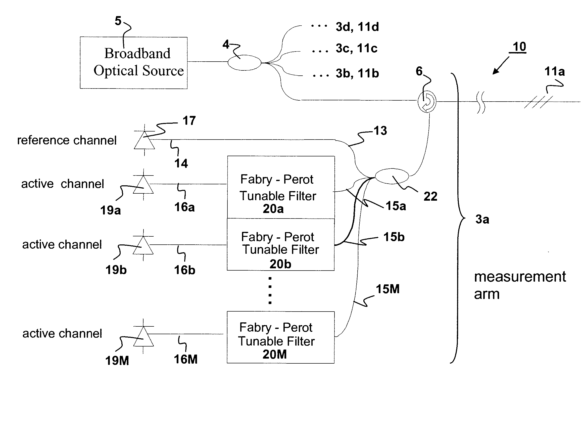
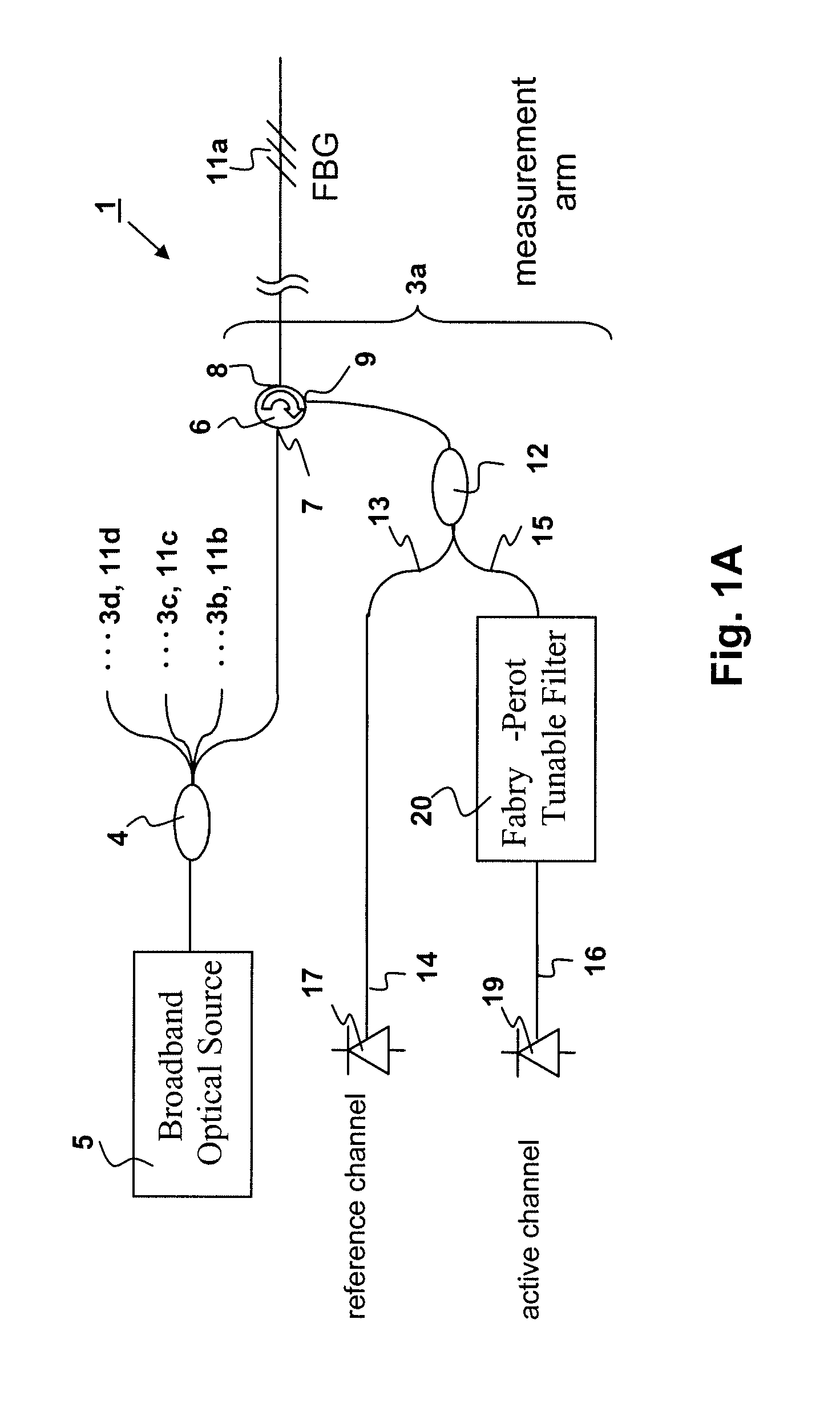
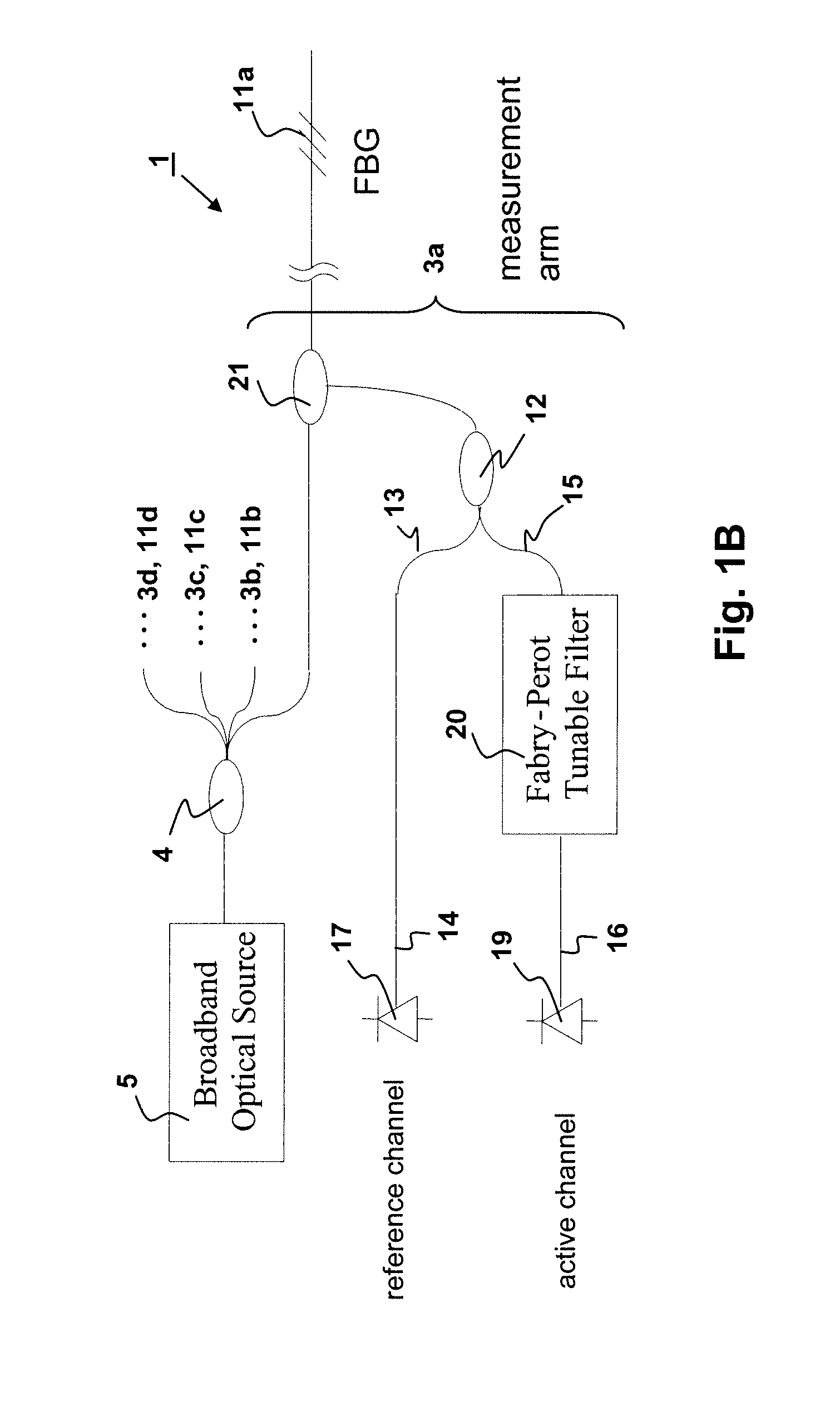
[0069]“Fiber Bragg Grating or FBG” refers to a periodic perturbation of the effective index of an optical fiber, yielding a narrow band reflection profile, the wavelength of which is sensitive to both temperature and strain. FBGs are used as sensing agents for both strain and temperature. FBGs (and optical sensors containing them) have a characteristic “Center Wavelength” which refers to the nominal peak reference wavelength of its reflection profile.

[0070] The term “optical sensor” refers generally to any class of optical component which reflects a specific narrowband optical spectrum that is affected by physical or environmental factors, such as strain, temperature, or other factors. Though the Fiber Bragg Grating is the most common and most obvious of such components, other components such as certain Fabry-Perot etalons can also function as optical sensors

[0071] Fiber optic sensors (also called optical fiber sensors) are fiber-based devices for sensing changes in some property ...


PUM


Abstract

Optical sensor measurement methods that convert a wavelength change in an optical sensor to a measurable optical intensity change, which can be calibrated and used to measure optical wavelength change and environmental changes such as temperature or strain which affect sensor wavelength. The current invention makes use of tunable fiber Fabry-Perot filters as the wavelength selective elements for the wavelength to optical intensity conversion. The invention provides high measurement sensitivities to small amplitude, high frequency modulations to the fiber sensor center wavelength, accommodates for system drift from thermal or other perturbations, and enables either frequency mode or time varying resolution of sensor modulation events. Selection of proper Fabry-Perot optics allow for measurement optimization of either high sensitivity or high strain measurement range.

Description

CROSS-REFERENCE TO RELATED APPLICATIONS [0001] This application takes priority from U.S. provisional application 60 / 824,266, filed Aug. 31, 2006, which is incorporated in its entirety by reference herein.BACKGROUND OF THE INVENTION [0002] In the past few years, fiber Bragg grating optical sensors have gained acceptance in the market as an alternative to conventional electronic gages. In many applications, including among others, civil structure monitoring, down hole oil and gas applications, marine and aerospace applications, fiber optic sensor systems offer several advantages over conventional gages. Unlike electronic sensors, fiber-based sensors are immune to electromagnetic interference and are well suited to electrically noisy environments. Fiber-based gages can be made very small and lightweight for use in confined spaces. Fiber-based gages can also be made to withstand high temperature and corrosive environments. [0003] Current fiber Bragg grating sensor systems are typically ...

Claims


Application Information

Patent Timeline
Patent Type & Authority Applications(United States)
IPC IPC(8): G01B9/02
CPCG01B11/18G01L1/246G01L1/242G01D5/35303G01D5/35316G01D5/35312
Inventor HABER, TODD C.MOCK, JOEL L.KRAUS, JAMES
Owner MICRON OPTICS
Why Eureka
Try Eureka