Advanced carbon dioxide fuel tank inerting system with desulfurization
a carbon dioxide and fuel tank technology, applied in the direction of liquid gas reaction process, machine/engine, chemical/physical process, etc., can solve the problems of nitrogen gas not supporting fuel vapor oxidation, fuel vapor and air existing in the fuel tank ullage (empty space above the fuel) can represent a significant threat, and the aircraft is destroyed and all on-board deaths are prevented
- Summary
- Abstract
- Description
- Claims
- Application Information
AI Technical Summary
Problems solved by technology
Method used
Image
Examples
example 1
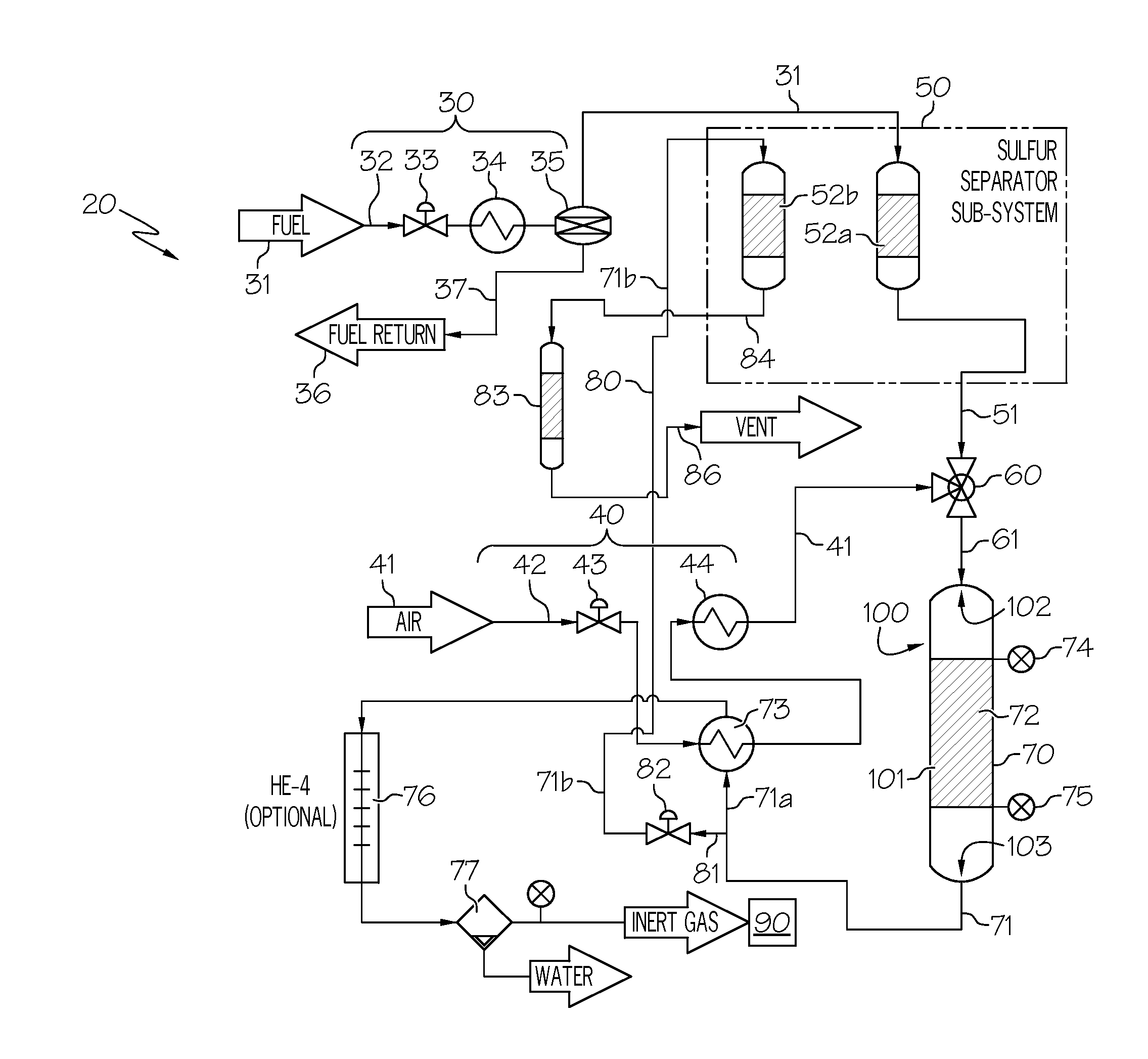
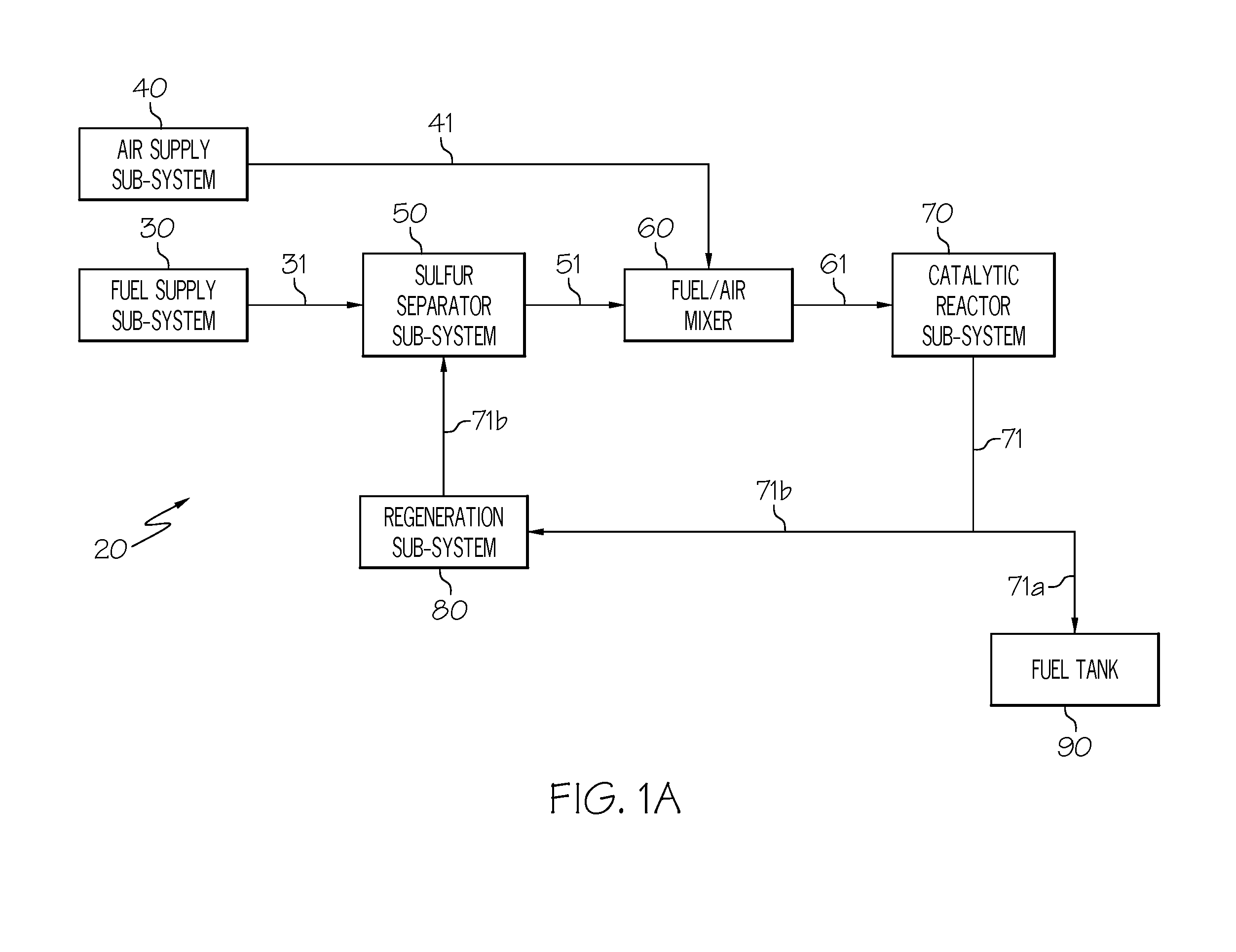
[0051]An embodiment of the system 20 is depicted in FIG. 2. In this example, the fuel 31 may be taken from the discharge side of a fuel pump, metered through the fuel valve 33 and then conducted (in liquid phase) to the adsorption column 52a, where sulfur-containing compounds are adsorbed onto a column of adsorbent. It is noteworthy that additional non-sulfur compounds such as polynuclear aromatics may also be retained but this represents only a reduction in total system efficiency. The desulfurized flow 51, which has substantially lower sulfur concentration than the fuel 31, is conducted to the fuel / air mixer 60. The supply of air 41 that has been collected from a bleed or compressor source, regulated by the air valve 43, heated by the recuperator heat exchanger 73, and heated by the air heater 44, is conducted to the fuel / air mixer 60. The combined fuel vapor and air stream has a composition well below the lower explosion limit of an air-fuel mixture and is conducted to the cataly...
example 2
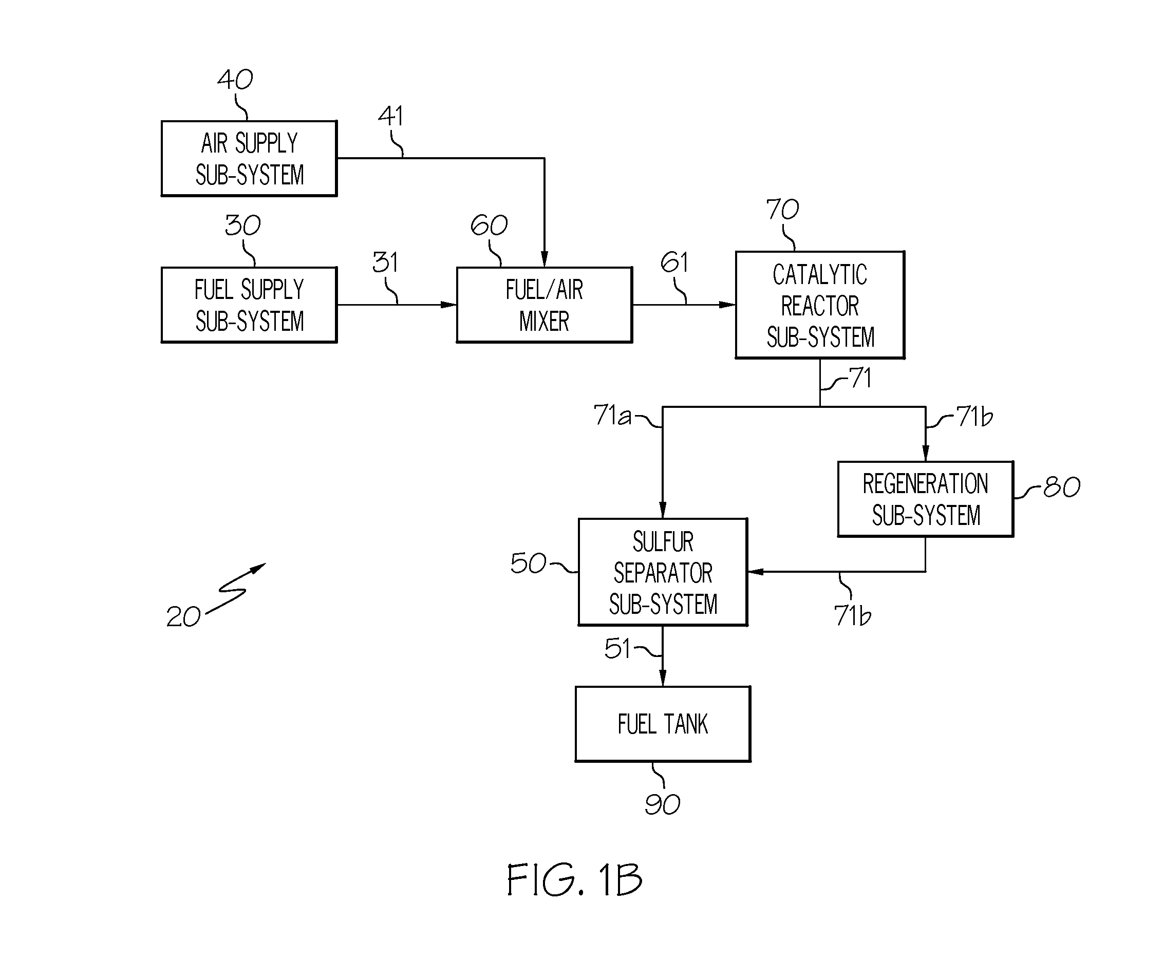
[0052]This example (see FIG. 4) describes how the fuel 31 and the air 41 can be combined prior to removal of sulfur compounds in the adsorption column 52a. A mixture of fuel and air is taken from the fuel tank ullage, metered through the fuel valve 33 and conducted to the sulfur separator sub-system 50, where sulfur-containing compounds are adsorbed onto a column of adsorbent. As noted in Example 1, additional non-sulfur compounds such as polynuclear aromatics may also be retained but this represents only a reduction in total system efficiency. The desulfurized flow 51, which has substantially lower sulfur concentration than the mixture from the fuel tank ullage, is conducted to the recuperator heat exchanger 73. The desulfurized flow 51 is heated by the recuperator heat exchanger 73, heated by the air heater 44, and conducted to the catalytic reactor 72. The combined fuel vapor and air stream has a composition well below the lower explosion limit of an air-fuel mixture. In the cata...
example 3
[0053]In this example (see FIG. 3), the fuel 31 may be taken from the discharge side of a fuel pump, metered through the fuel valve 33, heated in the fuel heater 34, and conducted to the evaporator 35, wherein a small fraction of the liquid fuel is vaporized. The remaining liquid fraction of the fuel is returned from the evaporator 35 to the fuel tank. The vapor phase from the evaporator 35 is conducted to the adsorption column 52a, where sulfur-containing compounds are adsorbed onto a column of adsorbent. As noted in Example 1, additional non-sulfur compounds such as polynuclear aromatics may also be retained but this represents only a reduction in total system efficiency. The desulfurized flow 51, which has substantially lower sulfur concentration than the fuel 31, is conducted to the fuel / air mixer 60. The supply of air 41 that has been collected from a bleed or compressor source, regulated by the air valve 43, heated by the recuperator heat exchanger 73, heated by the air heater...
PUM
| Property | Measurement | Unit |
|---|---|---|
| temperature | aaaaa | aaaaa |
| temperature | aaaaa | aaaaa |
| temperature | aaaaa | aaaaa |
Abstract
Description
Claims
Application Information
 - R&D
- Intellectual Property
- Life Sciences
- Materials
- Tech Scout
- Unparalleled Data Quality
- Higher Quality Content
- 60% Fewer Hallucinations
Browse by: Latest US Patents, China's latest patents, Technical Efficacy Thesaurus, Application Domain, Technology Topic, Popular Technical Reports.
© 2025 PatSnap. All rights reserved.Legal|Privacy policy|Modern Slavery Act Transparency Statement|Sitemap|About US| Contact US: help@patsnap.com


