Devices and Methods for Ultrasonic Imaging and Ablation

a technology of ultrasonic imaging and ablation, applied in the field of medical catheters and guidewires, can solve the problems of cto, inability to advance the guidewire, and halting the development of the device,

Inactive Publication Date: 2008-05-08
TOTAL WIRE CORP
View PDF5 Cites 262 Cited by
  • Summary
  • Abstract
  • Description
  • Claims
  • Application Information

AI Technical Summary

Benefits of technology

[0021]In another embodiment, a method includes: (1) causing laser light for ultrasonic imaging to be carried through a fiber-optic bundle of a device, (2) causing energy for ablation to be carried through an elongated member associated with the fiber-optic bundle, (3) causing the laser light for the ultrasonic imaging to be received into a distal cap having a glass element aligned with the fiber-optic bundle, (4) causing the laser light for the ultrasonic imaging to be substantially reflected off a reflective layer oriented at an acute angle with respect to the glass element, (5) causing the energy for ablation to be projected past the reflective layer and (6) causing at least some of the laser light for the ultrasonic imaging to be received by a photoacoustic layer associated with the glass element and converted into ultrasonic pressure waves.

Problems solved by technology

Chronic total occlusion (CTO) is a disease that remains difficult to treat interventionally due to the inherent nature of the disease and the lack of adequate tools and devices.
One of the major failure modes was inability of the guidewire to advance.
The development of the device halted due to safety concerns.
The catheter was unsuccessful due to safety concerns arising from the data that 30% of patients had extensive dissections.
In one clinical trial, the catheter was found to have a high rate of misalignment and perforation due to a stiff guidewire tip and a lack of guidance.
However, the Frontrunner™ is not suitable for the majority of coronary CTO cases due to poor steerability and the lack of guidance.
The device has had some success in recent clinical trials, but it is difficult to use and has yet to show widespread acceptance by interventionalists.
The issue with the Safe Cross™ guidewire is that the optical reflectometry system generates a warning signal so frequently that leaves the operator at a loss as to what to do.
Such a “negative” signal only tells the clinician what to avoid and fails to provide positive guidance for guidewire steering and advancement.
Furthermore, there is no definitive indication of whether the guidewire tip is intra-luminal or extra-luminal.
If for any reason the guidewire tip had accidentally perforated the vessel wall, the reflectometry signal would become useless.
A warning signal derived from laser induced fluorescence may have some advantages over the optical reflectometry signal, but the drawbacks are similar, namely, no geometric information about the diseased vessel.
Fluoroscopy is used to guide many procedures, but its efficacy in CTO intervention has proven to be rather limited.
Even with bi-plane projections, fluoroscopic images are hard to interpret for totally occluded vessel regions.
Another issue with excessive dependence on fluoroscopy arises from the fact that CTO procedures are often time-consuming.
Angioscopy requires flushing the blood and replacing it with saline, a procedure that requires temporarily occluding the blood vessel and can cause prolonged ischemia to the heart.
While IVUS would at first appear to be an attractive solution for guiding the advancement of a guidewire through a CTO, existing IVUS catheters have proven difficult to advance through occluded regions of calcified tissue or tissue having a significant degree of fibrosis.
For short occlusions, a clinician might be able to use a forward-looking IVUS to guide the advancement of the guidewire through the blockage, but even such forward-looking IVUS are still under development and not yet commercially available.
In addition, imaging through blood is very difficult even with carefully-chosen infrared wavelength for the light source.
Unfortunately, this device would be difficult to advance through a CTO, because the area that contains the ultrasonic transducer apparently is bulky and lacks the ability to ablate plaque.
In addition, Angelsen, et al., discloses no ability to perform forward imaging.
However, Morantte's catheter is apparently bulky and difficult to advance through CTOs.

Method used


Image

  • Devices and Methods for Ultrasonic Imaging and Ablation
  • Devices and Methods for Ultrasonic Imaging and Ablation
  • Devices and Methods for Ultrasonic Imaging and Ablation

Examples


Embodiment Construction

[0041]Several embodiments of the invention will now be described. Various structures, arrangements, relationships and functions may be asserted as being associated with or necessary to certain of the several embodiments. Those skilled in the pertinent art should understand, however, that those structures, arrangements, relationships and functions need not be associated with or necessary to the invention in general.

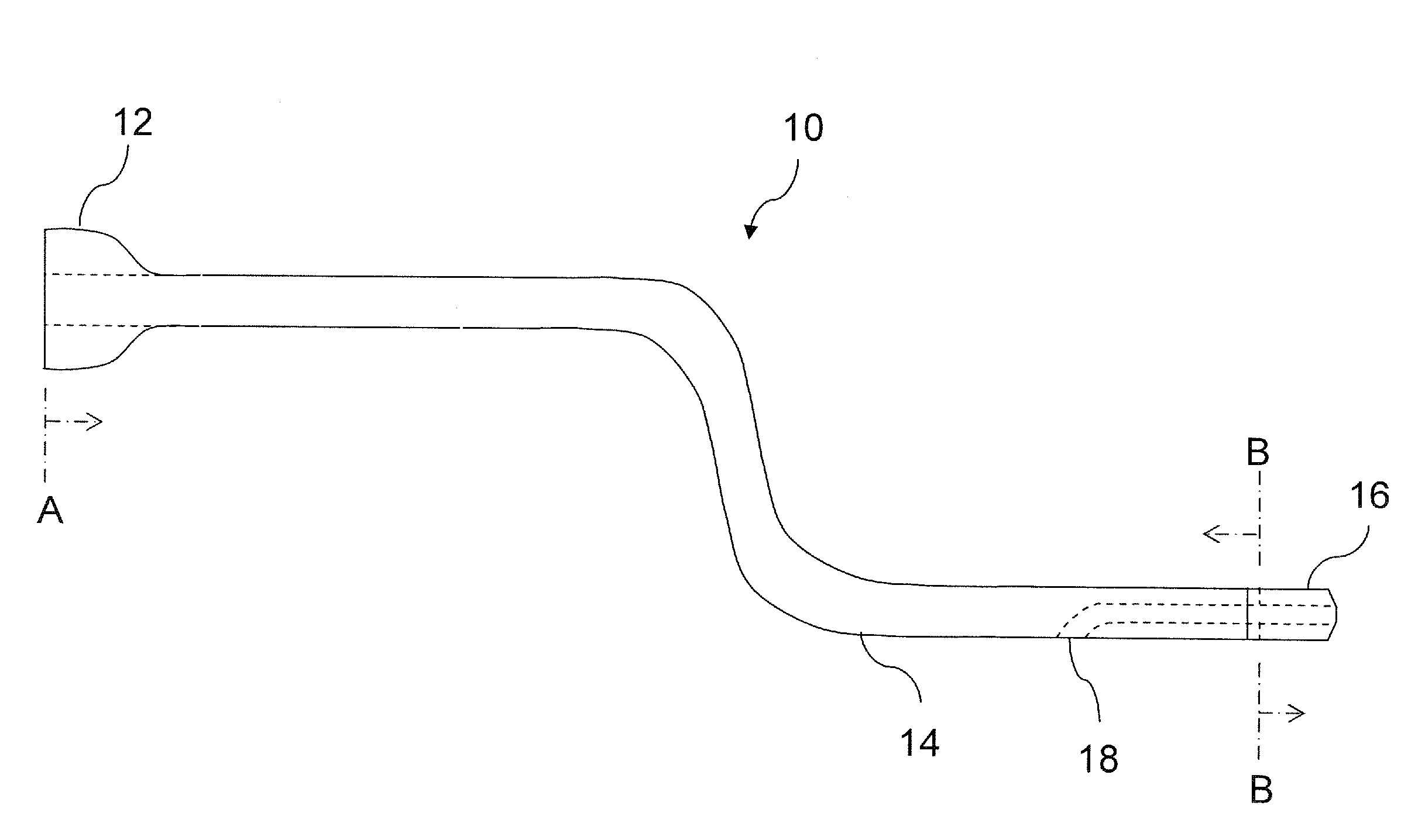
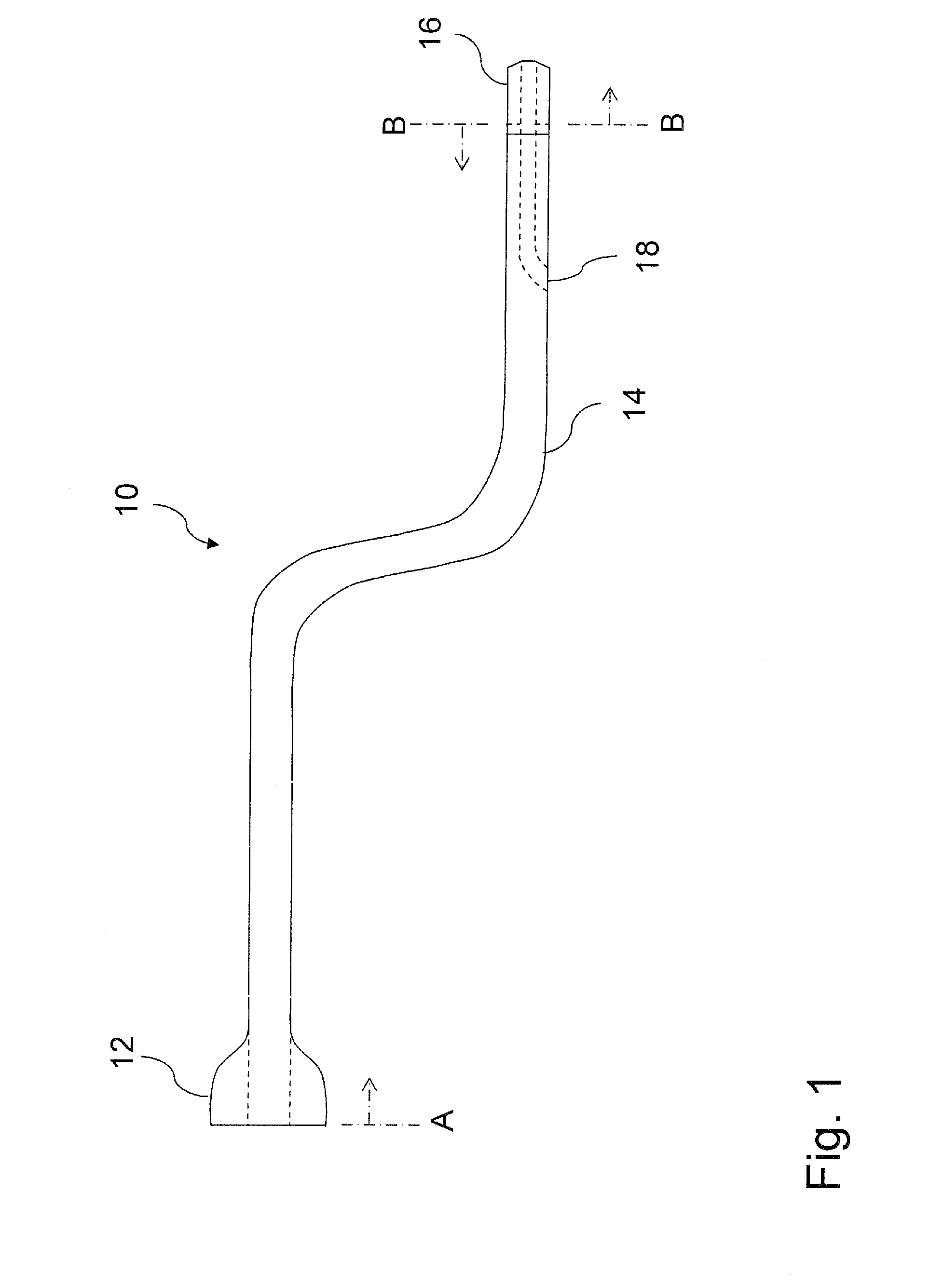
[0042]Referring initially to FIG. 1, illustrated is a schematic view illustrating one embodiment of a catheter 10 constructed according to the principles of the invention. The catheter 10 includes an elongated main body 14, a connector 12 at a proximal end thereof and a cap 16 affixed to the main body 14 at a distal end thereof. A guidewire lumen 18 is associated with the catheter 10. A plurality of optical fibers is embedded inside the catheter main body 14. The optical fibers extend from section A to section B in FIG. 1.

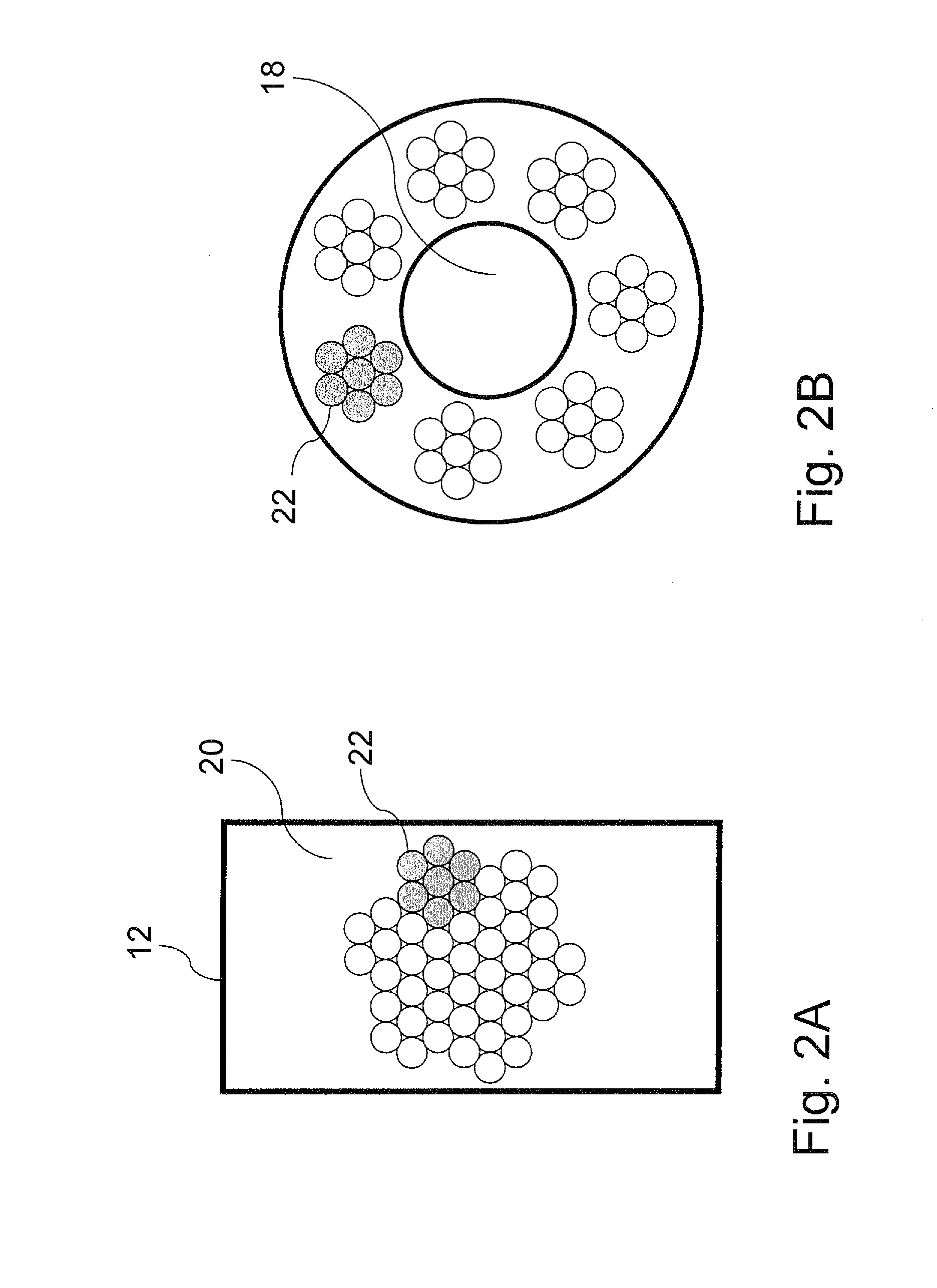
[0043]FIGS. 2A and 2B together show one embodiment ...


PUM


Abstract

Devices (i.e., catheters and guidewires) for, and methods of, ultrasonic imaging and ablation. In one embodiment, a device includes: (1) a fiber-optic bundle configured to carry laser light for ultrasonic imaging, each fiber of the fiber-optic bundle having a reflective layer oriented at an acute angle with respect thereto at a distal end thereof, (2) an elongated member associated with the fiber-optic bundle and configured to carry energy for ablation, the energy for ablation projecting past the distal end and (3) a photoacoustic layer associated with the each fiber of the fiber-optic bundle and configured to receive at least some of the laser light for the ultrasonic imaging and generate ultrasonic pressure waves in response thereto.

Description

CROSS-REFERENCE TO RELATED APPLICATION[0001]The present application claims priority based on U.S. Provisional Application Ser. No. 60 / 867,415, entitled “Catheter for Ultrasonic Imaging and Laser Ablation,” filed on Nov. 28, 2006, by Zhou, and further based on U.S. Provisional Application Ser. No. 60 / 884,241, also entitled “Catheter for Ultrasonic Imaging and Laser Ablation,” filed on Jan. 10, 2007, by Zhou, commonly owned with the present application and incorporated herein by reference. The present application is also a continuation-in-part of U.S. patent application Ser. No. 11 / 315,546, entitled “Image-Guided Laser Catheter,” filed on Dec. 22, 2005, by Zhou, commonly owned with the present application and incorporated herein by reference.TECHNICAL FIELD OF THE INVENTION[0002]The invention relates generally to the field of medical catheters and guidewires and more specifically to devices, taking the form of either catheters or guidewires, and methods for ultrasonic imaging and abla...

Claims


Application Information

Patent Timeline
Patent Type & Authority Applications(United States)
IPC IPC(8): A61B1/00A61B18/18A61N1/00
CPCA61B5/02007A61B8/12A61B8/4483A61B8/4488G10K15/046A61B2018/00577A61B2018/2272A61B2019/528G01S15/8965A61B18/245A61B2090/3784
Inventor ZHOU, GAN
Owner TOTAL WIRE CORP
Why Eureka
Try Eureka