Methods and Systems for Determining Volume Flow in a Blood or Fluid Conduit, Motion, and Mechanical Properties of Structures Within the Body

a technology of volume flow and blood or fluid conduit, applied in the field of hemodynamics, can solve the problems of frequent occurrence of malfunction of such an access in patients receiving chronic hemodialysis, reduced blood flow, undesired recirculation

Inactive Publication Date: 2008-05-08
RGT UNIV OF MICHIGAN
View PDF6 Cites 66 Cited by
  • Summary
  • Abstract
  • Description
  • Claims
  • Application Information

AI Technical Summary

Problems solved by technology

While a permanent vascular access provides a convenient connection site for arterial and venous lines, malfunction of such an access is a frequent occurrence in patients receiving chronic hemodialysis.
Specifically, unpredictable thrombosis and stenosis in an access causes a reduction in blood flow which necessitates correction through angioplasty or other surgical means.
If untreated, low blood flow can cause undesired recirculation in the access, where some part of the freshly dialyzed blood from the venous line flows upstream to the arterial line where it is again filtered.
Studies have shown that decreased hemodialysis access flow is associated with an increased risk of access thrombosis and stenosis, such that early detection of an access with a low flow rate is essential in order to prevent more serious complications (see May et al., Kidney Int. 52: 1656-1662, 1997).
Unfortunately, occlusion of the access may lead to thrombosis, and placement of the needle or pressure sensor within the access is invasive.
However, these methods do not correlate well enough with blood flow rate and lack the sensitivity and specificity needed for accurate access surveillance.
However, Doppler ultrasound techniques are fraught with sources of operator error, most often associated with the determination of cross-sectional area as well as assumptions about the velocity profile.
In addition, conventional Doppler ultrasound is labor intensive and expensive, such that measurements are not usually made with high enough frequency to effectively monitor the onset of reduced access flow.
This dilutes the flow of blood in the access, resulting in Doppler velocity changes measured by the ultrasonic sensor on the arterial line.
Unfortunately, conditions affecting indicator mixing and recirculation of the indicator through the cardiovascular system can affect the accuracy of results using this method.
Furthermore, due to the necessity for the reversal of blood lines during dialysis, dilution techniques are cumbersome and time-consuming.

Method used


Image

  • Methods and Systems for Determining Volume Flow in a Blood or Fluid Conduit, Motion, and Mechanical Properties of Structures Within the Body
  • Methods and Systems for Determining Volume Flow in a Blood or Fluid Conduit, Motion, and Mechanical Properties of Structures Within the Body
  • Methods and Systems for Determining Volume Flow in a Blood or Fluid Conduit, Motion, and Mechanical Properties of Structures Within the Body

Examples


experiment i

[0105]An vitro study was performed to determine the differential intra-luminal pressure (? P) and flow (Q) relationships in geometry dependent models mimicking arteriovenous graft (AVG) vascular circuits to explore the future development of implantable or extra-corporeal devices using differential pressures to estimate flow for dialysis access monitoring. ? P and Q were obtained using AVG inner diameters of 4.76 mm, 6.35 mm, and 7.95 mm, at separation distances from 2.5 cm to 20 cm, with flows ranging from 0 to 1968 ml / min. Mean and standard deviation values were compared with linear (Poiseuille's), and second order polynomial (Young's) models to model laminar and turbulent flow patterns respectively. Experimental ? P measurement ranged from ±0.015 to 46.95=±0.568 mmHg for the range of studied access diameters at flows from 65 to 1968 mL / min. In conclusion, differential intra-luminal pressure may be useful in flow estimation for dialysis conduits in future implantable or extracorpor...

experiment ii

Materials and Methods

Experimental System

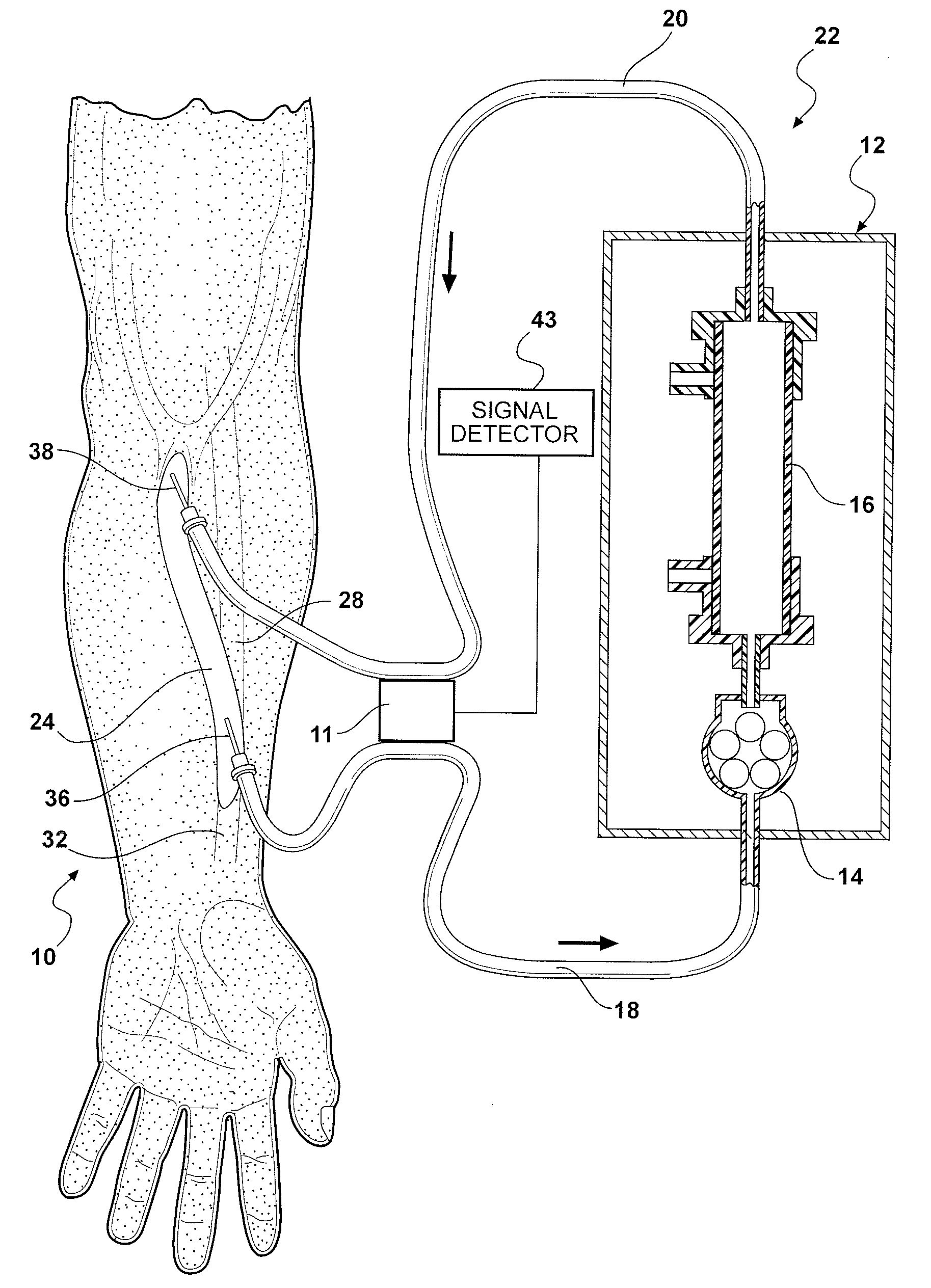
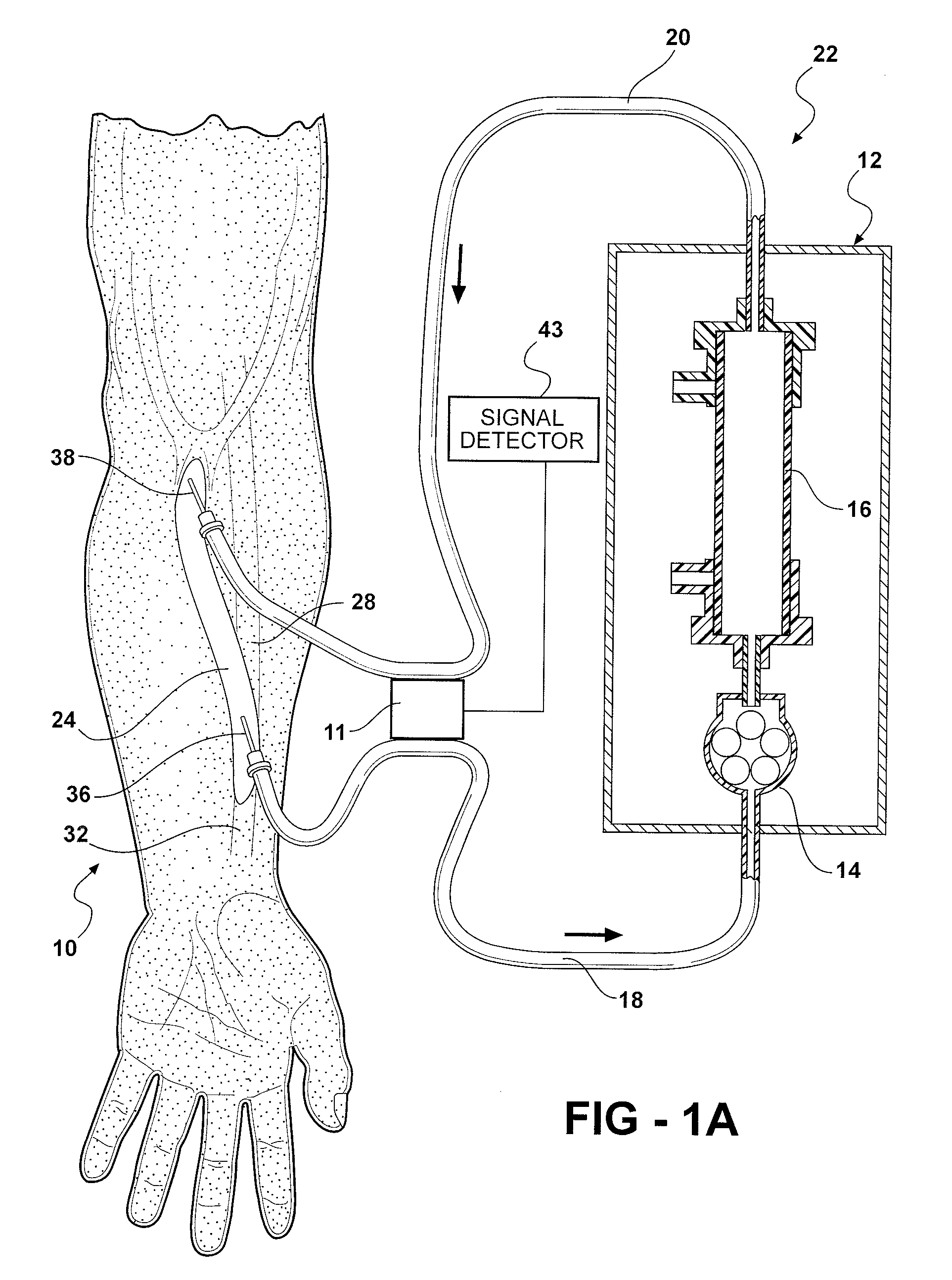
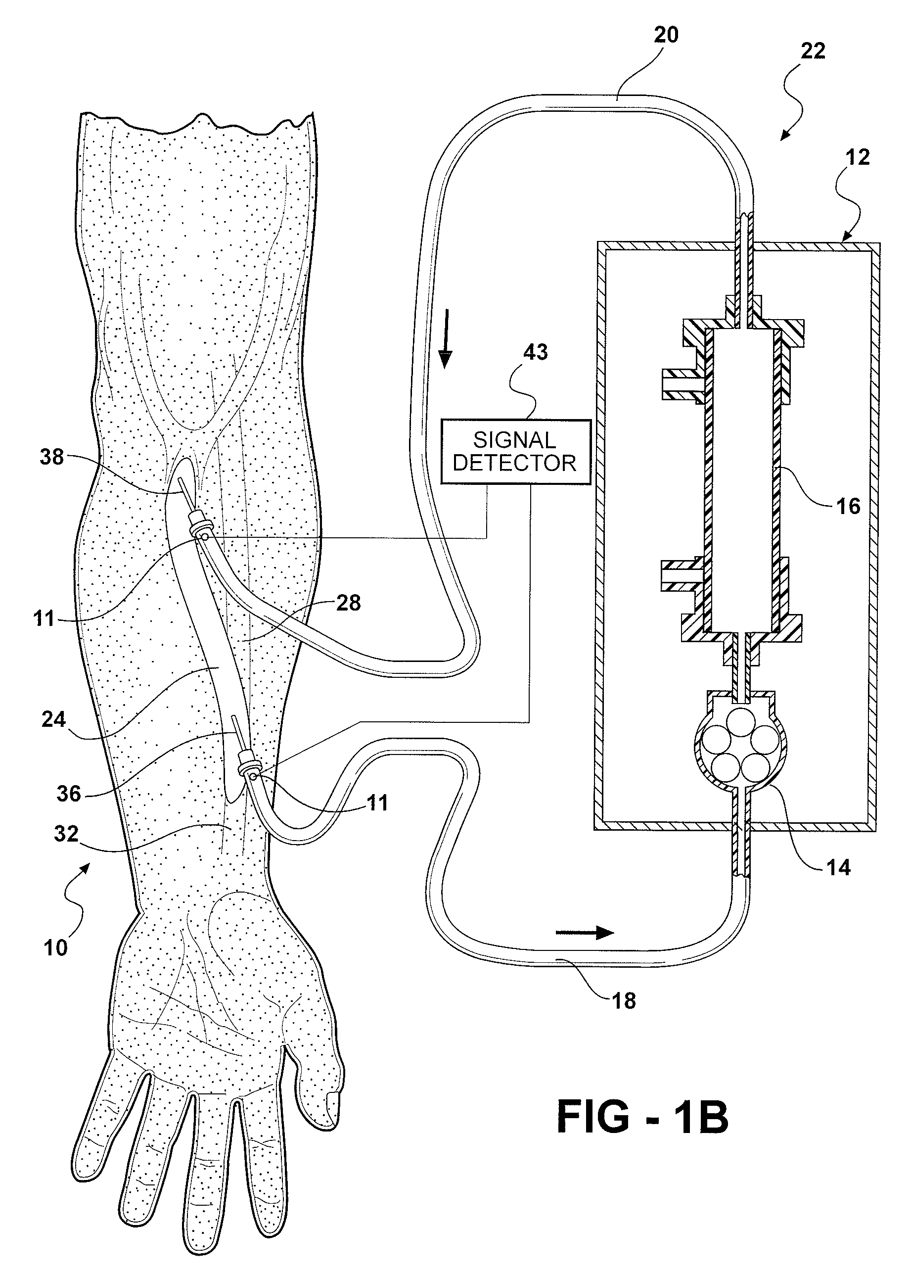
[0121]A laboratory flow phantom system was constructed using two parallel fluid conduits to simulate the patient blood circuit communicating in parallel with the dialysis blood pump circuit to test the geometry independent algorithms for flow determination. In these experiments, different access diameters were used (4.76 mm and 6.35 mm inner diameter) to approximate arteriovenous graft inner diameters, as well as a glycerol-containing solution to simulate the viscosity of blood at 37% hematocrit. The dialysis circuit was assembled to generate measurable flow rates with an adjustable non-pulsatile roller pump (Masterflex Cole Parmer, Vernon Hills, Ill. Console Drive Model 7520-40) with flow rates measured using a McMillan (Georgetown, Tex.) S-110 digital flowmeter and a Gilmont flow meter (Thermo Fisher Scientific) which was calibrated in our laboratory to ensure the accuracy of simulated dialysis pump speeds ranging from zero to 500 ml / min. Th...


PUM

PropertyMeasurementUnit
diameteraaaaaaaaaa
diameteraaaaaaaaaa
pressureaaaaaaaaaa

Abstract

The present invention provides a system for determining blood flow rate in a vessel which communicates blood between two locations of a patient, the system comprising: a conduit in fluid communication with the vessel; at least one sensor in communication with the vessel for determining differential blood pressure (? P) between two or more locations within the vessel; and a processor operably connected to the at least one sensor for processing the ? P to obtain blood flow rate within the vessel.A method for determining blood flow rate in a vessel which communicates blood between two locations of a patient, the method comprising: diverting blood from the vessel at a diversion point to obtain a flow of diverted blood in a conduit; determining differential blood pressure (? P) of the diverted blood through the conduit; and processing the ? P to obtain blood flow rate within the vessel.

Description

CROSS-REFERENCE TO PRIORITY APPLICATION[0001]This application claims benefit of U.S. Provisional Application No. 60 / 856,589, entitled “Methods and Systems for Determining Volume Flow in a Blood or Fluid Conduit, Motion, and Mechanical Properties of Structures Within the Body” and filed Nov. 3, 2006, the content of which is incorporated herein by reference in its entirety.STATEMENT REGARDING FEDERALLY SPONSORED RESEARCH OR DEVELOPMENT[0002]The invention was made with Government support under NIH Grant No. 5 K08 DK062848-02. The Government has certain rights to the invention.BACKGROUND OF THE INVENTION[0003]This invention relates to the field of hemodynamics, and more particularly to a system and method for measuring blood flow rate in a vessel, such as a hemodialysis access.[0004]Hemodialysis is a process by which blood is passed through an external dialysis circuit to replace the function of a patient's kidney. Blood is removed from the patient's vascular system via an arterial line...

Claims


Application Information

Patent Timeline
Patent Type & Authority Applications(United States)
IPC IPC(8): A61M1/34B01D61/24
CPCA61B5/02152A61B5/026A61M1/3656A61M1/3639A61M1/3655A61M1/16A61M2205/3344A61M2205/3331A61M1/3607A61M2205/3334A61M1/36A61M2205/3375
Inventor WEITZEL, WILLIAM F.GIANCHANDANI, YOGESH B.
Owner RGT UNIV OF MICHIGAN
Why Eureka
Try Eureka