Rotation Detecting Apparatus and Bearing Provided With Same

a technology of rotating detecting device and bearing, which is applied in the direction of galvano-magnetic hall-effect device, galvano-magnetic device, instrument, etc., can solve the problems of residual offset variation still affecting angle detection, difficulty in allowing magnetic sensor, degradation of angle detecting precision, etc., to reduce increase angle detecting accuracy of rotation detecting device, reduce the effect of offset variation of magnetic sensor elements

Inactive Publication Date: 2008-05-15
NTN CORP
View PDF14 Cites 4 Cited by
  • Summary
  • Abstract
  • Description
  • Claims
  • Application Information

AI Technical Summary

Benefits of technology

[0049]According to this construction, by operating the magnetic sensor elements forming the magnetic sensor array in the linear region, it is possible to reduce the offset variation of the magnetic sensor elements. Yet, the influence brought about by the en...

Problems solved by technology

However, in the structure in which the magnetic encoder 54 is provided in the manner as hereinabove described, in the case of a small diameter bearing, which is a rolling bearing assembly of a small size, problems have been recognized in that it is difficult to allow the magnetic sensor 55 to be accommodated within the outer diametric size of the stationary ring 53 and, also, to detect the rotation angle with high precision enough to secure the number of rotation pulses that is equal to or greater than 500 per each complete rotation.
However, in the case of this construction, in a semiconductor circuit, it is unavoidable for circuit elements, integrated on a silicon chip, to result in variation in characteristic and offset variations of the sensor elements tend to occur even in the magnetic sensor array, thus constituting a cause of degradation of the angle detecting precision.
However, even though the magnetic sensor elements are arranged in parallel relation to each other, the residual offset variation still affects the angle detection.
However, the current difference generated from the magnetic sensor element is so ...

Method used


Image

  • Rotation Detecting Apparatus and Bearing Provided With Same
  • Rotation Detecting Apparatus and Bearing Provided With Same
  • Rotation Detecting Apparatus and Bearing Provided With Same

Examples


first embodiment

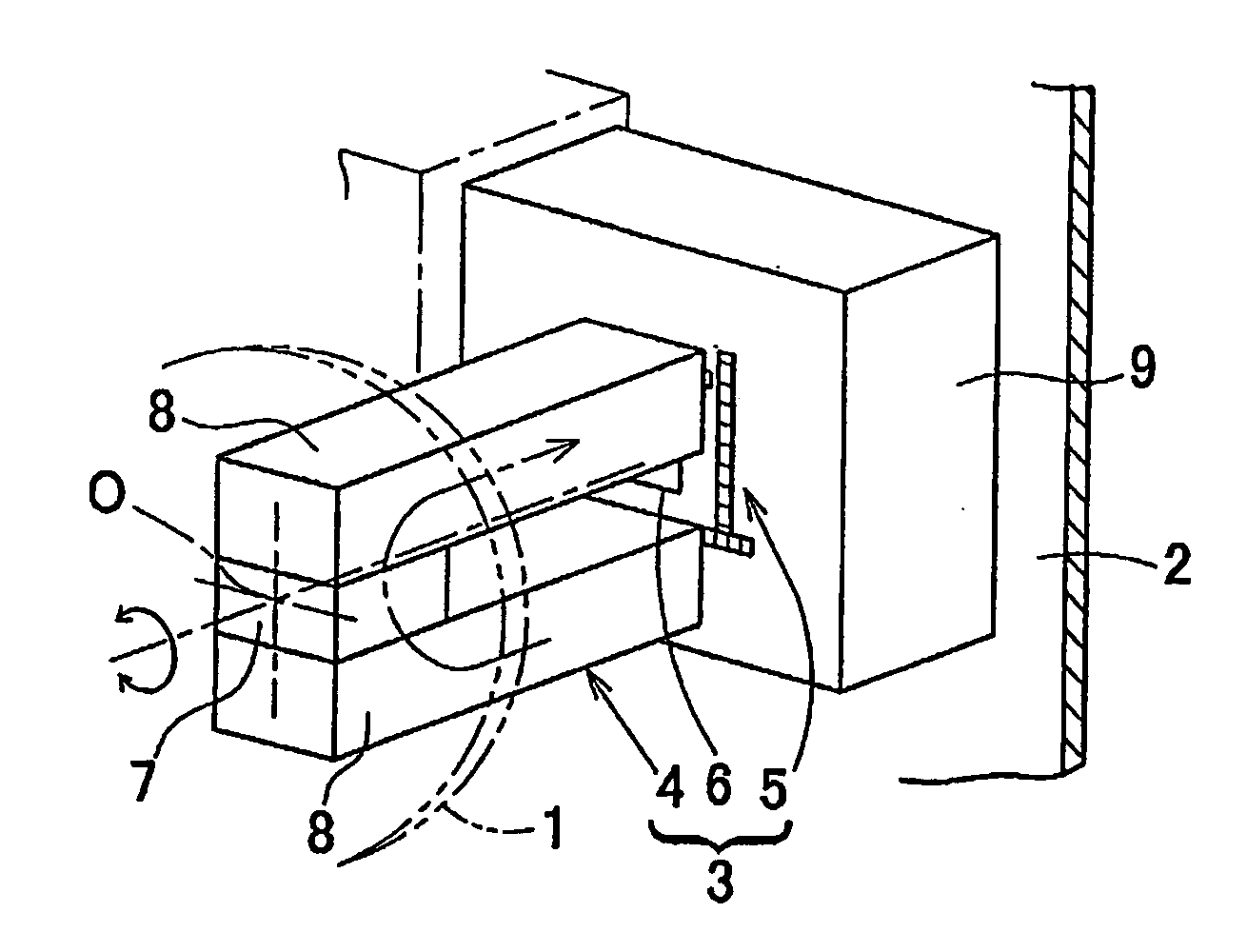
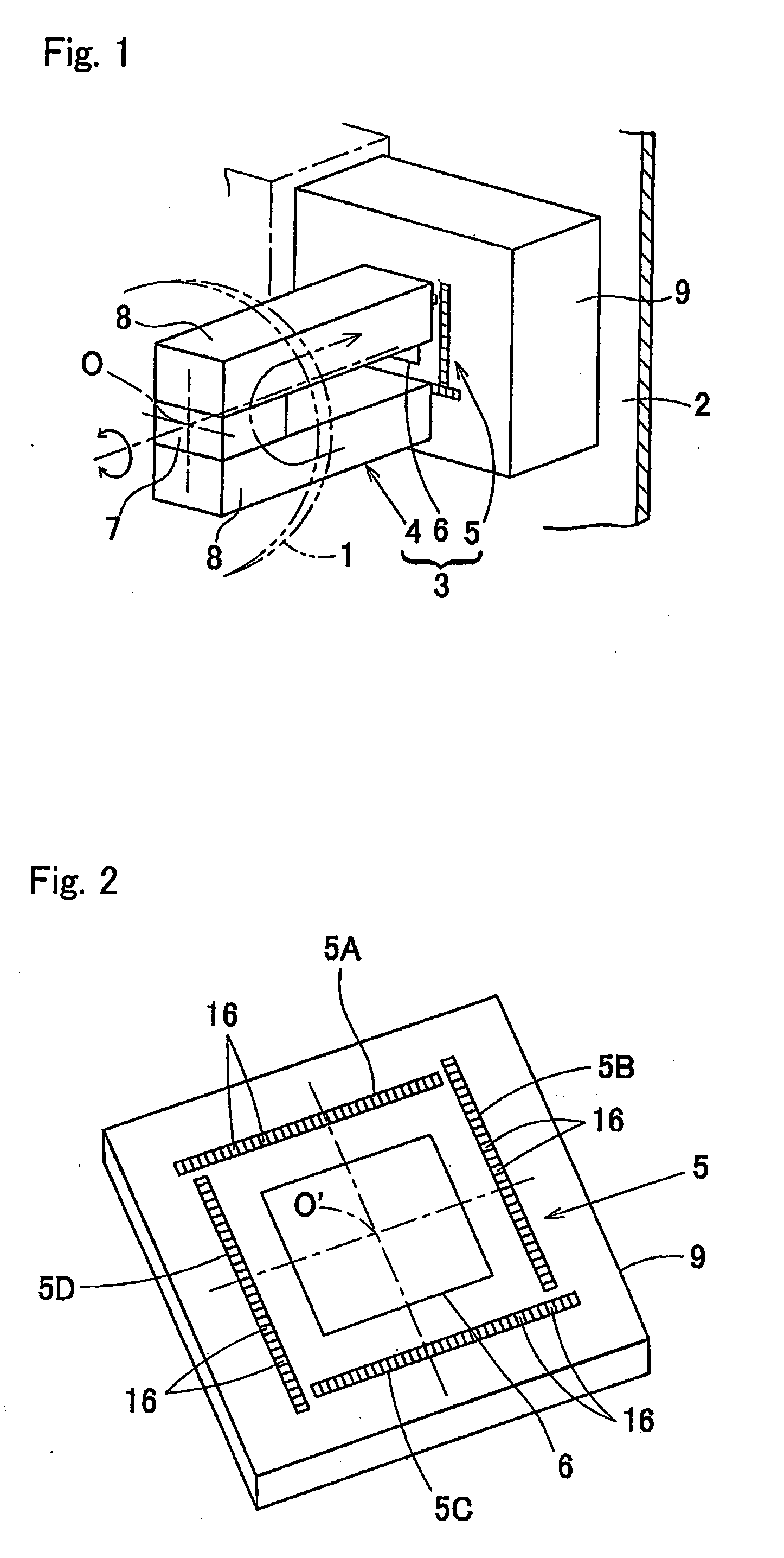
[0094]A rotation detecting apparatus according to a first preferred embodiment of the present invention will be described with reference to the accompanying drawings. FIG. 1 illustrates the principle of the rotation detecting apparatus according to the present invention. A rotatable member 1 and a non-rotatable member 2 represent, respectively, members on rotatable and non-rotatable sides that rotate relative to each other and, more specifically, the rotatable member 1 is represented by a rotating raceway ring of a bearing assembly and the non-rotatable member 2 is represented by a stationary raceway ring of the bearing assembly. This rotation detecting apparatus 3 includes a magnet 4, which forms a magnetic generating element arranged on the rotatable member 1, a magnetic sensor array 5 arranged on the non-rotatable member 2, and an angle calculating unit 6 for calculating the rotation angle of the magnet 4 from an output of the magnetic sensor array 5. The magnetic sensor array 5 ...

third embodiment

[0165]FIGS. 25 and 26 illustrate a fourth preferred embodiment of the present invention and are circuit block diagrams showing a condition of selection of the reference sensor element used in the magnetic array sensor circuit 61. The magnetic array sensor circuit 61 is similar to that employed in the practice of the third embodiment shown in FIG. 19, but differ therefrom in that in place of the use of the control circuit (regulating circuit) 18 for operating the magnetic sensor elements 51 to 5n in the linear region, the use is made of a regulating circuit 18A including the reference sensor element 5ref. FIG. 25 illustrates a condition in which the sensor selecting unit 19B selects the reference sensor element 5ref and FIG. 26 illustrates a condition in which the sensor selecting unit 19B selects one of the other magnetic sensor elements 51 to 5n (for example, the magnetic sensor element 51 so far shown therein).

[0166]The regulating circuit 18A of the magnetic array sensor circuit 6...

fourth embodiment

[0168]The magnetic array sensor circuit 61 in this fourth embodiment is of a type provided with the reference sensor element 5ref, the offset output storage element 97 and the analog subtraction circuit 98 for the sake of protecting the rotation detecting apparatus from being easily affected by such environmental change as discussed above.

[0169]The reference sensor element 5ref is, as a part of the magnetic sensor array 5, arranged together with the magnetic sensor elements 51 to 5n and can be selected by the sensor selecting unit 19B for operation. Other structural features are substantially similar to that employed in the embodiment shown in and described with reference to FIG. 19.

[0170]In this magnetic array sensor circuit 61, the output signal is processed in the following manner:[0171](1) As shown in FIG. 25, when the sensor selecting unit 19B selects the reference sensor element 5ref and read out the sensor signal of the reference sensor element 5ref, since the reference senso...


PUM


Abstract

To provide a rotation detecting apparatus capable of increasing the angle detecting precision without being affected by an offset signal resulting from a stress in a silicon chip, the rotation detecting apparatus 3 includes a magnetic sensor array 5 and a magnet 4 rotatable in face-to-face relation with the magnetic sensor array 5. The magnetic sensor array includes a plurality of groups 16 of sensor elements each group 16 including four sensor elements. The four sensor elements 5a to 5d of each combined sensor element group 16 are so arranged as to be oriented vertically and horizontally in four directions and connected parallel to each other.

Description

BACKGROUND OF THE INVENTION[0001]1. Field of the Invention[0002]The present invention relates to a rotation detecting apparatus for detecting the rotation of various machines and equipments such as, for example, for detecting the rotation for controlling rotation of a compact motor, or for detecting the rotation for detecting the position within a business equipment, and also to a bearing assembly equipped with such rotation detecting apparatus.[0003]2. Description of the Prior Art[0004]Taking advantage of the compactness and the easiness of assemblage, a bearing assembly having a rotation sensor built therein has hitherto been suggested. One example of such bearing assembly is shown in FIG. 29. In this example, a rotating ring 52 of a rolling bearing assembly 51 is fixed with a member including a magnetic encoder 54 in the form of rubber magnets having a plurality of alternating magnetic poles N and S deployed in a circumferential direction thereof, and a stationary ring 53 is fixe...

Claims


Application Information

Patent Timeline
IPC IPC(8): G01B7/30
CPCG01D5/145
Inventor TAKAHASHI, TORUKAWAHITO, SHOJI
Owner NTN CORP
Why Eureka
Try Eureka