Coil Device and Magnetic Field Generating Device

a technology of magnetic field and coil device, which is applied in the direction of electric/magnetic/electromagnetic heating, prosthesis, therapy, etc., can solve the problems of increasing resistance, too much energy will be lost, and energy loss caused by skin effect induced in current path becomes problematic, etc.

Inactive Publication Date: 2008-05-15
KANAZAWA UNIV
View PDF13 Cites 19 Cited by
  • Summary
  • Abstract
  • Description
  • Claims
  • Application Information

AI Technical Summary

Benefits of technology

[0005]In order to heat the magnetic fluid having been injected into the affected portion to around 43 degree C., it is necessary to apply large current of high frequency to a resonance circuit connected to the secondary side of a transformer. In applying large current of high frequency to a bread-shaped coil as a magnetic field generating means, however, energy loss caused by the skin effect induced in the current path becomes problematic. According to an analysis carried out by the inven...

Problems solved by technology

In applying large current of high frequency to a bread-shaped coil as a magnetic field generating means, however, energy loss caused by the skin...

Method used


Image

  • Coil Device and Magnetic Field Generating Device
  • Coil Device and Magnetic Field Generating Device
  • Coil Device and Magnetic Field Generating Device

Examples


Embodiment Construction

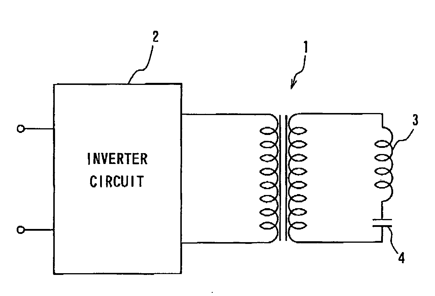
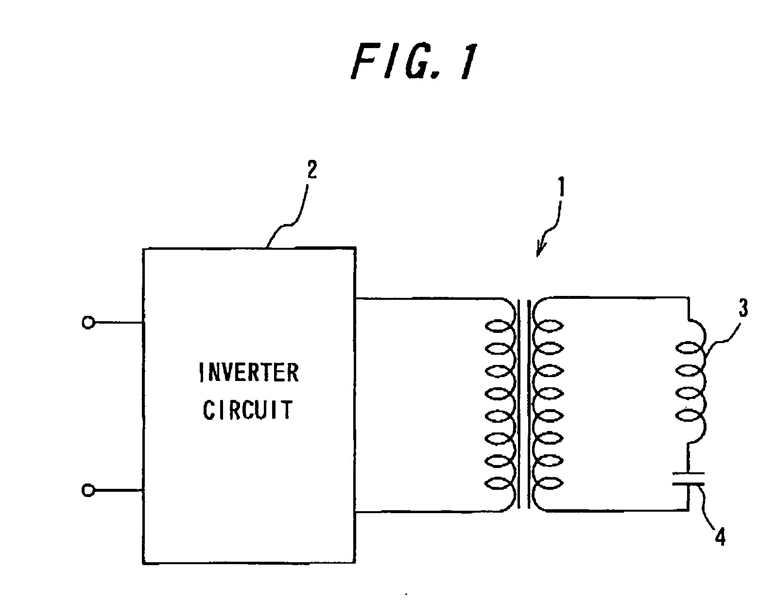
[0021]FIG. 1 is a diagram showing a circuit constitution of the magnetic field generating device of the present invention. An inverter circuit 2 comprising a semiconductor switching element is connected to the primary side of a transformer 1 to generate an alternate output of a predetermined frequency. A resonance circuit comprising a coil 3 as a magnetic field generating means and a resonance condenser 4 series-connected to each other is connected to the secondary side of the transformer 1. The alternate output is configured to have a substantially same frequency as the resonance frequency of the series resonance circuit on the secondary side. The magnetic field generating device transmits energy from the primary side to the secondary side through electromagnetic induction, generates an alternate magnetic field from the coil 3 and irradiates a magnetic flux to the affected portion of the patient. To the coil 3 on the secondary side is applied for instance a current of 300 A and 5 k...


PUM


Abstract

Problems to be solved: to provide a coil device and a magnetic field generating device with reduced energy loss that are suitable for use in the thermotherapy method.
Means for solving the problem: a coil device according to the present invention can be used in a magnetic field generating device for the thermotherapy method in which a magnetic flux is irradiated to the patient to selectively heat a specific portion of the patient. Said coil device is a bread-shaped coil device having a current path extending in the shape of a spiral in a substantially same plane, said current path comprising a hollow cylindrical member (10) of a nonmagnetic material inside which a space is formed and a plurality of conductive wires (11, 12) covered with an insulation material on the peripheries thereof. In the present invention, the current path comprising a plurality of conductive wires covered with an insulation material which are arranged in a circle, energy loss caused by the skin effect and energy loss caused by the line capacity can be reduced, making it possible to generate a strong magnetic field. Also, by using the hollow cylindrical member (10), it is possible to easily configure a current path in a predetermined diameter and to inhibit increase in temperature of the coil (3) to avoid fluctuation of the resonance frequency of the resonance circuit. With this, a magnetic field generating device that is suitable for use in thermotherapy, particularly cancer therapy, can be realized.

Description

FIELD OF THE INVENTION[0001]The present invention relates to a coil device, particularly to a coil device with drastically reduced energy loss. The present invention further relates to a magnetic field generating device used for induction heating therapy, particularly to a magnetic field generating device with reduced energy loss.BACKGROUND OF THE INVENTION[0002]The thermotherapy (hyperthermia) method is attracting attention as a method for cancer therapy. By this thermotherapy method, attention is focused upon the fact that a cancer cell or a cancerous tissue is more vulnerable to heat than a healthy cell. By heating the cancer-affected portion for example to 43 degree C. for a certain length of time, the cancer lesion can selectedly be necrotized. In this thermotherapy method, an aqueous sol of magnetic fluid such as a complex of dextran or its derivative and magnetic iron oxide is injected into the affected portion, to which a strong magnetic field is applied from outside to sele...

Claims


Application Information

Patent Timeline
IPC IPC(8): A61F7/00A61N1/40A61N2/02H05B6/10H05B6/36
CPCA61N1/403H05B6/362A61N2/02
Inventor NAGANO, ISAMUIKEHATA, YOSHIO
Owner KANAZAWA UNIV
Why Eureka
Try Eureka