
Mobile transit fare payment

Active Publication Date: 2008-05-22
VISA USA INC (US)
View PDF100 Cites 208 Cited by
  • Summary
  • Abstract
  • Description
  • Claims
  • Application Information

AI Technical Summary

Benefits of technology

[0015]Further, because the mobile device, alone or in conjunction with the network, may incorporate location determining technologies, data relevant to a particular transit system may be provided as a user moves between different locations, regions, or cities. In addition, operations required to configure the chip, either in terms of data storage (partitions, indexing, data management) or functional capabilities, may be accomplished via the network as a form of over-the-air provisioning. This eliminates the need for a user to visit a transit office or kiosk to activate the smart card's functionality, obtain the access control data or obtain other information needed prior to using a specific transit system.

Problems solved by technology

This requirement is inefficient and sub-optimal as transit users are often in a hurry, and do not wish to wait in lines or engage in a formal transaction process that may require more time than desired for authentication of the user and approval of the transaction.
Even though contactless smart cards provide a solution to some of the problems encountered by standard payment cards in a transit fare payment and collection environment, they do not provide a complete solution.
This means that the transit fare payment and collection process can not be performed effectively using a standard on-line authentication and approval process, as may be used for a purchase transaction at a retail point of sale through the financial payment network.
This presents a difficulty because effective fraud prevention typically requires authentication that the card user is entitled to access the transit system and has sufficient funds for the desired transaction.
This can become a significant problem if a user wishes to utilize more than one transit system, such as two transit agencies within a single geographical area or transit systems in two different cities or locations.
Thus, the transit environment presents several issues that make use of a standard contactless smart card or chip problematic.
In addition to those noted, these issues include:A need for one card per transit agency or group of cooperating agencies;If a contactless payment card is used, it typically lacks the ability to write back to the chip, and data is not available on subsequent transactions to calculate the fare.
This adds to the burden of the system having to keep track of card history and calculate the fare in a post processing system rather than at the gate or farebox;It may be required that a patron, who is visiting a location or agency for the first time may need to register their card for use in that system.
This may take a physical process of going and doing something before the card may be used in transit at the new location; andEach agency or region may utilize a different set of file structures and / or information to handle their fare policy, and a single card may lack the appropriate data formats or encryption capability.

Method used


Image

  • Mobile transit fare payment
  • Mobile transit fare payment
  • Mobile transit fare payment

Examples


first embodiment

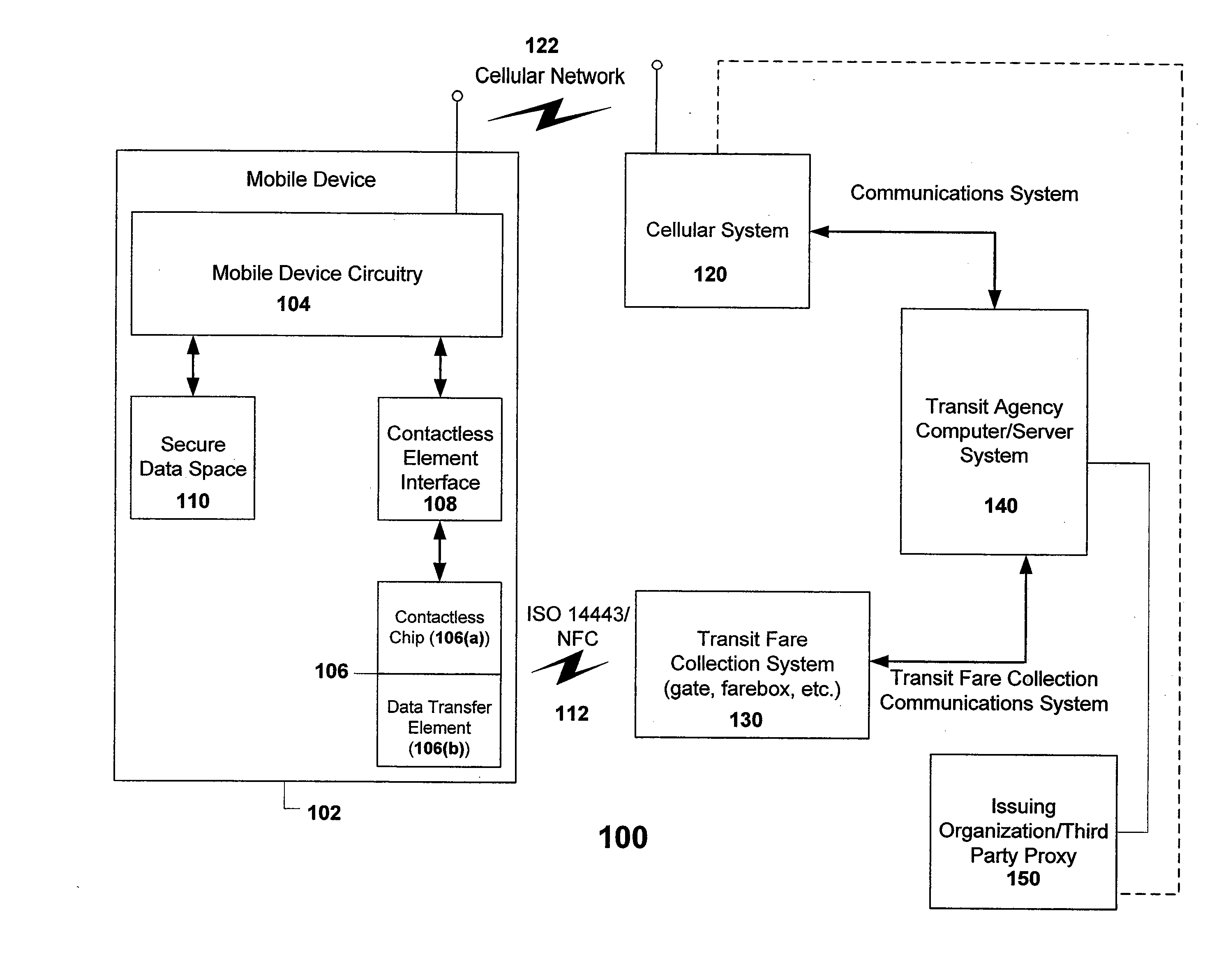
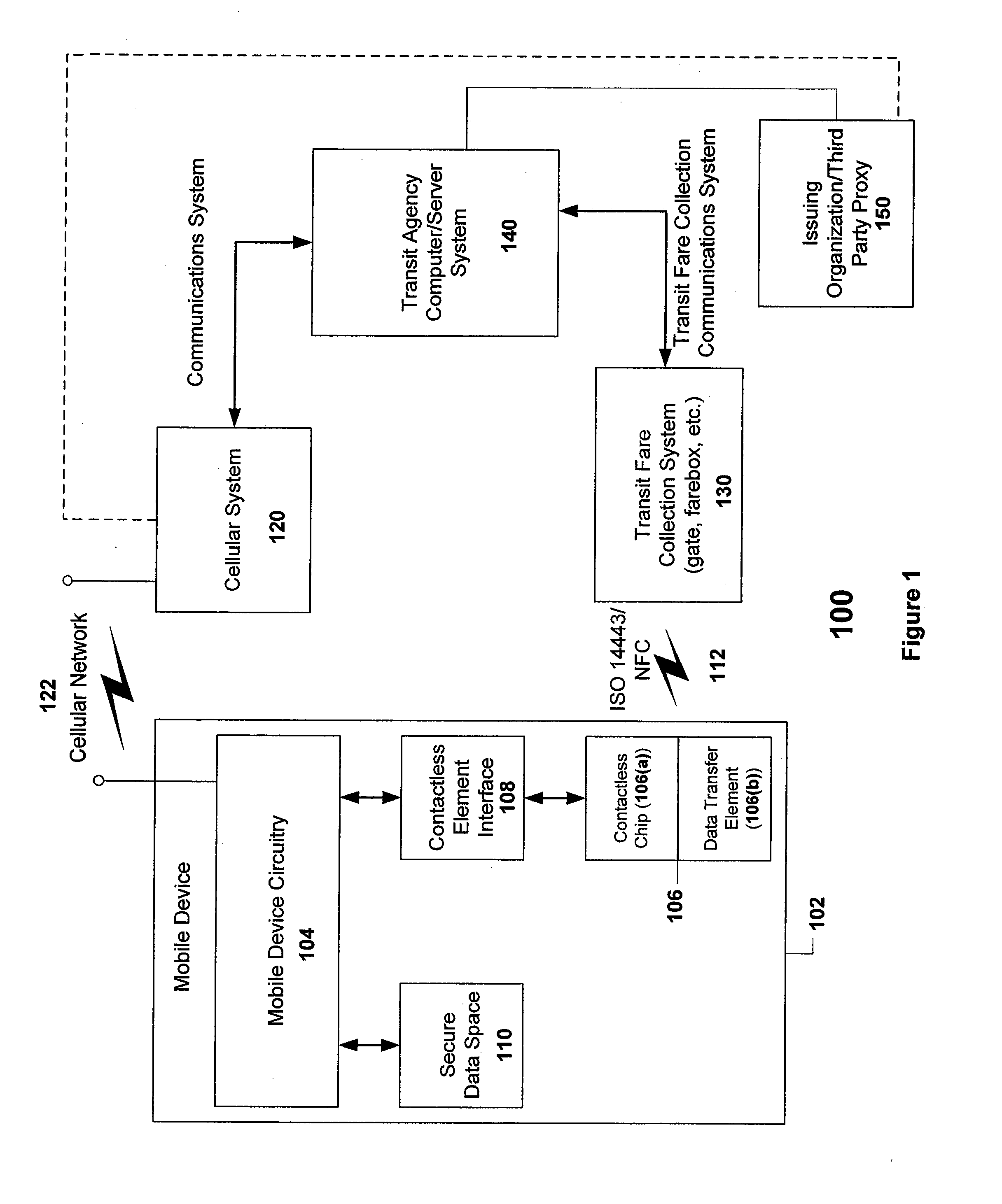
[0037]FIG. 1 is a functional block diagram of a system 100 for enabling a contactless element contained within a mobile device to be used in the fare payment and collection environment, in accordance with an embodiment of the present invention. As shown in FIG. 1, system 100 includes a mobile device 102 having wireless communications capabilities 122. Mobile device 102 may be a wireless mobile telephone, PDA, laptop computer, pager, etc. In a typical embodiment, mobile device 102 is a cell phone, although as noted, implementation of the present invention is not limited to this embodiment. In the case of a cell phone as the mobile device 102, the device includes mobile device (cell phone) circuitry 104 that enables certain of the telephony functions. Mobile device circuitry 104 is capable of communicating wirelessly with cellular system (i.e., a wireless carrier) 120 via cellular network 122.

[0038]Mobile device 102 further includes a contactless element 106, typically implemented in ...

second embodiment

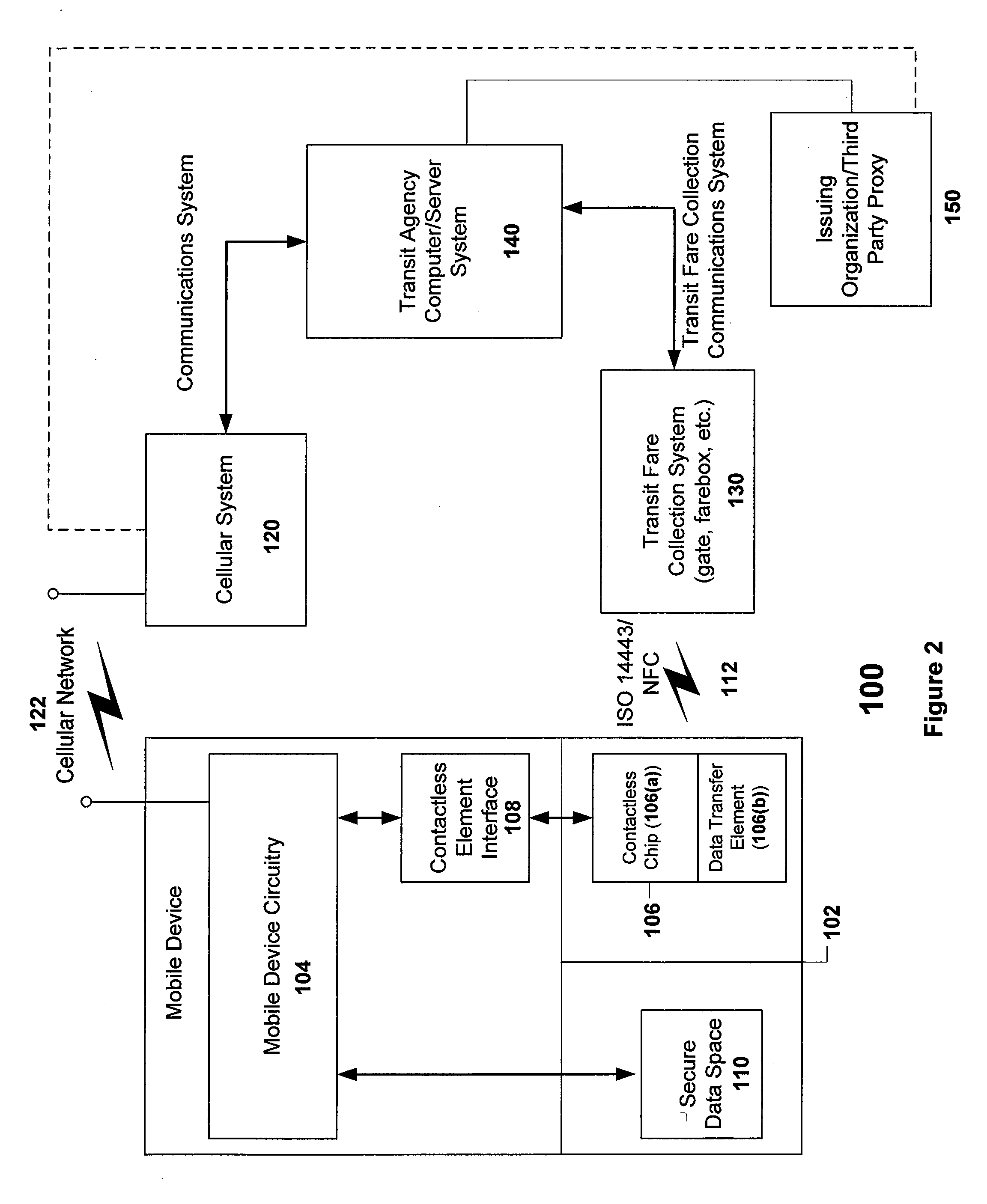
[0042]FIG. 2 is a functional block diagram of a system for enabling a contactless element contained within a mobile device to be used in the fare payment and collection environment, in accordance with an embodiment of the present invention. FIG. 2 shows the same elements as FIG. 1, with the exception that the secure data space and / or contactless element contained within the mobile device are depicted as removable elements instead of being integrated within the mobile device, as depicted in FIG. 1. Examples of such removable elements include SIM cards, flash memory cards, and other suitable devices.

[0043]As described, inventive system 100 provides an efficient means of using a contactless element in a transit or other environment. By integrating the contactless element with the mobile device's telephony communications capabilities, the cellular network may be used as the data transfer channel between a Transit Agency's computing system and the transit system user's mobile device. Thi...


PUM


Abstract

A system, apparatus, and method for facilitating the payment and collection of transit system fares using a mobile device. The inventive system utilizes a contactless element embedded within a mobile wireless device, such as a mobile phone, PDA, or the like. The smart element is integrated with the circuitry of the mobile device to permit the data to be accessed and manipulated (e.g., read, written, erased) using the wireless communications network as the data transport channel. The data required to enable a user to access a transit system and for the system to conduct fare calculations may be provided to the memory in the contactless element using the wireless network. Such data may include access control data (keys, passwords, identification data) or data required for fare calculations (rates, historical data on system use).

Description

BACKGROUND OF THE INVENTION[0001]The present invention is directed to systems, apparatuses and methods for the payment and collection of transit fares, and more specifically, to a system and associated apparatus and method that utilizes a mobile device such as a cell phone to enable payment of a transit fare. The present invention is further directed to systems, methods and apparatuses for using a contactless element such as an integrated circuit chip embedded in a wireless mobile device that may combine transaction payment and transit fare payment capabilities.[0002]Many people regularly commute to work or travel for other purposes using transportation systems. Such systems include public transportation systems, for example, buses, subways, trains, ferries, and the like. Typically, these transportations systems require some form of fare payment at one or more sites of the system. One means of fare payment is the use of some form of payment card, from which a fare can be deducted ag...

Claims


Application Information

Patent Timeline
IPC IPC(8): G06K5/00G07B15/00G05B19/00G07B15/02
CPCG06Q20/045G06Q20/32G06Q20/322G07F17/0014G06Q20/3278G07B15/00G07B15/02G06Q20/327G06Q20/4015
Inventor HAMMAD, AYMANDIXON, PHIL
Owner VISA USA INC (US)
Features
  • Generate Ideas
  • Intellectual Property
  • Life Sciences
  • Materials
  • Tech Scout
  • Unparalleled Data Quality
  • Higher Quality Content
  • 60% Fewer Hallucinations
Learn More