Transonic compressor rotors with non-monotonic meanline angle distributions

a compressor rotor and non-monotonic technology, applied in the direction of machines/engines, supersonic fluid pumps, liquid fuel engines, etc., can solve the problems of weaken or remove shock waves, and achieve the effect of improving compressor airfoil design, high efficiency and high operability

Inactive Publication Date: 2008-05-22
SIEMENS ENERGY INC
View PDF12 Cites 51 Cited by
  • Summary
  • Abstract
  • Description
  • Claims
  • Application Information

AI Technical Summary

Benefits of technology

[0009]According to one embodiment of the invention, a high efficiency and high operability (stall margin) gas turbine engine is provided through improved compressor airfoil designs. The airfoil shapes at different span locations are designed to satisfy flow angle turning for the needed work input, as determined by the Euler work equation. The invention provides improved airfoils that more efficiently turn the fluid flow from a tangential (rotation) direction to an axial direction to achieve passage area expansion and flow diffusion.
[0010]According to one embodiment, the invention provides improved fluid flow in the passages between airfoils and higher efficiency by providing airfoils that include non-monotonic meanline slope angles for reducing the peak Mach number in the passages. The improved airfoils with the non-monotonic meanline slope angles may also weaken or remove the shock waves.
[0011]According to another embodiment, the invention provides improved fluid flow in the passages and higher operability by providing airfoils with non-monotonic meanline slope angles that reduce fluid separation at the airfoil.
[0012]According to another embodiment, the invention provides a non-monotonic meanline angle distribution technique with local negative camber applied to a transonic rotor blade from the hub region to the tip region, wherein the negative camber is provided downstream of the throat so as not to reduce mass flow through the rotor section.

Problems solved by technology

The improved airfoils with the non-monotonic meanline slope angles may also weaken or remove the shock waves.

Method used


Image

  • Transonic compressor rotors with non-monotonic meanline angle distributions
  • Transonic compressor rotors with non-monotonic meanline angle distributions
  • Transonic compressor rotors with non-monotonic meanline angle distributions

Examples


Embodiment Construction

[0025]While specific embodiments of the invention are discussed herein and are illustrated in the drawings appended hereto, the invention encompasses a broader spectrum than the specific subject matter described and illustrated. As would be appreciated by those skilled in the art, the embodiments described herein provide but a few examples of the broad scope of the invention. There is no intention to limit the scope of the invention only to the embodiments described.

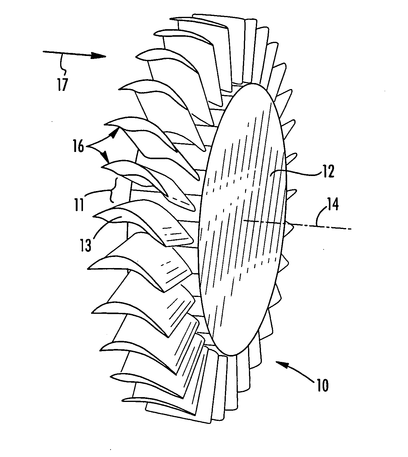
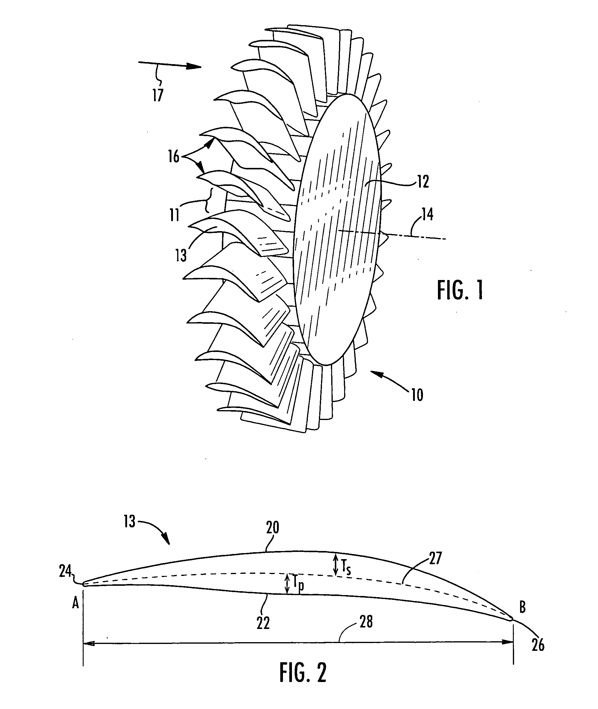
[0026]According to one embodiment of the invention illustrated in FIG. 1, a compressor rotor assembly 10 is provided for a gas turbine. The compressor rotor assembly 10 includes a rotor hub 12 that rotates about an axis 14. A plurality of rotors 16 extend outwardly from the rotor hub 12. According to one embodiment, the rotors 16 extend in a radial direction away from the rotor hub 12. Fluid 17 flows axially along direction 17 and passes between adjacent rotors 16 at passages 11. The rotors 16 are defined by airfoils 13,...


PUM


Abstract

Airfoils are provided having non-monotonic meanline angle distributions and local negative camber along a length of the meanline between a point on a leading edge of the airfoil and a point on the trailing edge of the airfoil. The improved airfoil shape decreases the peak of a Mach number of a shock wave that develops in a passage between adjacent airfoils and attenuates or eliminates the shock wave at the suction surface of the airfoil within the passage. A blade constructed by this type of airfoil provides improved fluid flow in the passages between the airfoils, increased efficiency and an improved stall margin, among other benefits.

Description

FIELD OF THE INVENTION[0001]This invention is directed generally to axial flow rotary machines having transonic airfoils. More particularly, the invention is directed to combustion turbine engines having transonic compressor rotors or fans with non-monotonic meanline angle distributions.BACKGROUND[0002]Combustion turbine engines include three main components: a compressor for compressing a fluid, such as air; a combustor for mixing the compressed fluid with fuel and igniting the mixture; and a turbine for producing power. These components are generally configured in series and are sealed to form a gas-tight system.[0003]The compressor, fan and turbine components typically contain many rows of opposing airfoil-shaped blades that are grouped in stages. In the compressor component, the stages typically include a row of rotating blades (rotors) followed by a row of stationary blades (stators), as viewed from a direction of fluid flow from an inlet side to an outlet side. In the turbine ...

Claims


Application Information

Patent Timeline
Patent Type & Authority Applications(United States)
IPC IPC(8): F01D5/14F04D29/38
CPCF01D5/141F05D2240/301F04D29/324F04D21/00
Inventor HU, ZONGJUNZHA, GECHENG
Owner SIEMENS ENERGY INC
Why Eureka
Try Eureka