Flow Rate Measurement Apparatus

a flow rate measurement and flow rate technology, applied in the field of flow rate measurement apparatus, can solve the problems of high cost, troublesome and expensive sterilization of the apparatus every time the apparatus is used, and high cost of disposing of materials, so as to reduce the flow rate, simplify the apparatus structure, and secure the effect of safety

Inactive Publication Date: 2008-05-22
KONICA MINOLTA MEDICAL & GRAPHICS INC
View PDF4 Cites 13 Cited by
  • Summary
  • Abstract
  • Description
  • Claims
  • Application Information

AI Technical Summary

Benefits of technology

[0007]An object of the present invention is to simplify the apparatus structure, provide a less expensive flow rate measurement apparatus and secure the safety in view of the problems associated with the prior art described above.

Problems solved by technology

However, since the configuration of the apparatus was complicated, the flow rate measurement apparatus of the prior art described above has been often expensive.
However, to sterilize the apparatus every time the apparatus is used is not only troublesome but also expensive because of the expenditure required for the consumptions and disposal of an antiseptic.
When a sensor and an expensive material for measuring the respiration flow rate are used in the exhalation path, there has been a problem that to dispose these materials makes the cost high.
Thus, there has been a problem when measuring the flow rate of the fluid having toxic or infected fluid.

Method used


Image

  • Flow Rate Measurement Apparatus
  • Flow Rate Measurement Apparatus
  • Flow Rate Measurement Apparatus

Examples


first embodiment

[0106]The first embodiment of the present invention will be described by referring to drawings. However, the present invention is not limited to the examples illustrated in Figures.

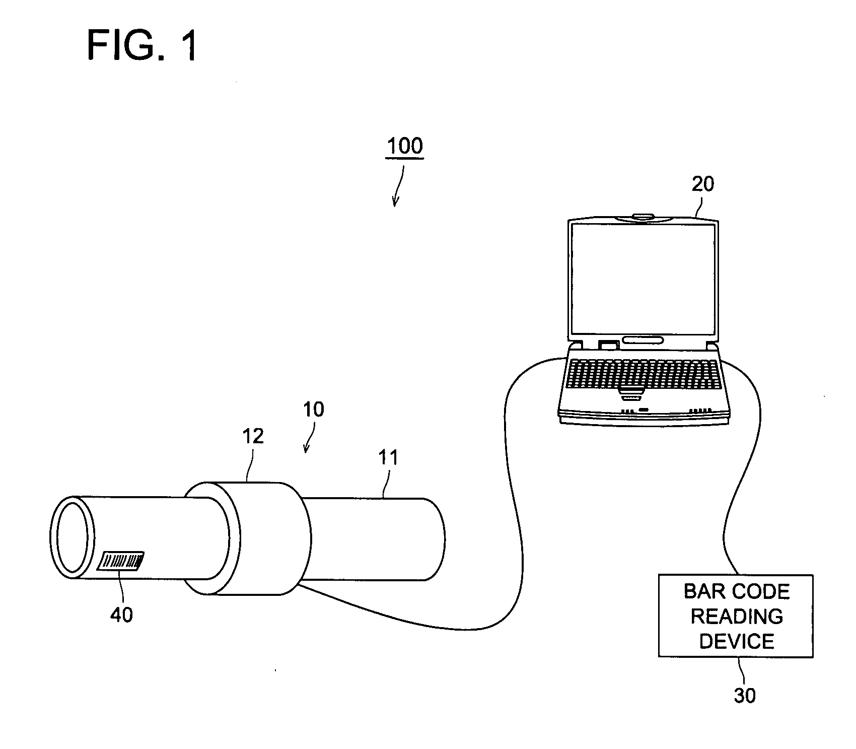
[0107]FIG. 1 illustrates a schematic configuration of the respiration flow rate measurement apparatus 100 of the first embodiment. The respiration flow rate measurement apparatus 100 is configured by a measurement section 10, a PC (Personal Computer) 20 and a bar code reading device 30.

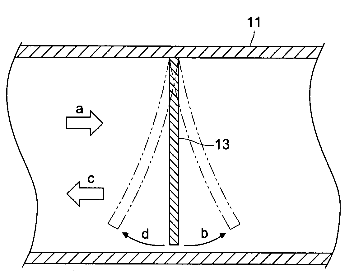
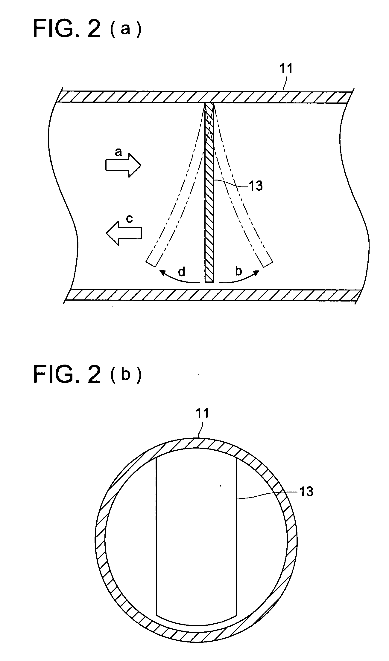
[0108]The measurement section 10 includes a pipe 11 and a holder section 12. The pipe 11 is configured by a cylindrically structured transparent resin and the pipe 11 forms a path, through which respiration gas flows. The pipe 11 and the holder section 12 are structured to be detachable. The holder section 12 and the PC 20 are directly connected or connected through a network.

[0109]Further, a bar code 40 is adhered onto the pipe 11 as identification information for individually identifying a movable member 13, which will be...

second embodiment

[0137]Next, the second embodiment of the present invention will be described.

[0138]The respiration flow rate measurement apparatus of the second embodiment is structured by a pipe 11a and a movable member 13a instead of the pipe 11 and the movable member 13 of the first embodiment. The other structures are the same as the first embodiment. Accordingly, the drawings and the descriptions will be omitted. The characterized structure associated with the second embodiment will be described below.

[0139]FIG. 6(a) illustrates a longitudinal cross sectional view of a pipe 11a when cutting the pipe 11a in the second embodiment of the present invention in an axial direction. FIG. 6(b) illustrates a vertical cross sectional view when cutting the pipe 11a in a radius direction at X-X line of FIG. 6(a). In the first embodiment, the top portion of the movable member 13 is fixed inside the pipe 11. However, in the second embodiment, the lower portion of the movable member 13a is fixed inside the pi...

third embodiment

[0147]Next, the third embodiment of the present invention will be described.

[0148]The respiration flow rate measurement apparatus of the third embodiment is structured by a pipe 11b and a movable member 13b instead of the pipe 11 and the movable member 13 of the first embodiment. The other structures are the same as the first embodiment. Accordingly, the same symbol will be used for the same part of the structure, and the drawings and the descriptions will be omitted. The characterized structure of the third embodiment will be described below.

[0149]FIG. 8(a) illustrates a longitudinal cross sectional view of a pipe 11b when cutting the pipe 11b of the third embodiment of the present invention in an axial direction. As shown in FIG. 8(a), the movable member 13b having a spherical shape is arranged to move along the shaft 16, which is passed through the hole structured at the center of the spherical movable member 13b. The movable member 13b is connected with springs 17 of elastic bod...


PUM


Abstract

A movable member 13, whose physical change occurs corresponding to a respiration flow rate, is disposed in the pipe 11. The pipe 11 and holder section are structured to be capable of being detachable. When staring respiration with the mouth touching pipe 11, the movable member 13 bends corresponding to respiration flow rate. Image data of the movable member 13 is obtained through the pipe 11 by a CCD area sensor disposed outside the pipe 11 and the bending amount is detected. The respiration rate is calculated based on the flow rate data corresponding to the bending amount of the movable member 13 in use.

Description

TECHNICAL FIELD[0001]The present invention relates to a flow rate measurement apparatus for measuring the flow rate in a flowing path, through which fluid flows.BACKGROUND OF THE INVENTION[0002]In the inspection of a patient having respiratory diseases, a lung function inspection is an important inspection as well as image diagnosis including CT (Computed Tomography) and X-ray photography, and blood inspection. The lung function inspection is conducted almost always when conducting diagnosis of the patient having chronic respiratory diseases, such as, pulmonary emphysema, bronchial asthma and bronchiectasis. In recent years, COPD (Chronic Obstructive Pulmonary Disease) has attracted a great deal of attention. The number of latent patients having COPD is estimated to be several millions. The lung function inspection is very important in the inspections for this disease. In the medical checks conducted at physical training gymnastics, measurements of, such as, a lung capacity, tidal v...

Claims


Application Information

Patent Timeline
Patent Type & Authority Applications(United States)
IPC IPC(8): A61B5/087
CPCA61B5/0876G01F1/28A61B2562/085A61B2562/08
Inventor WADA, YASUNORI
Owner KONICA MINOLTA MEDICAL & GRAPHICS INC
Why Eureka
Try Eureka