Method and system for the design of an enclosure to house internal components

a technology for enclosures and internal components, applied in the field of enclosures, can solve the problems of insufficient tools for efficient enclosure design, difficult and time-consuming process, and many electronic engineers not having the tools required to efficiently design enclosures, etc., and achieve the effect of short time and simple use and learning

Active Publication Date: 2008-05-22
PROTOCASE
View PDF28 Cites 35 Cited by
  • Summary
  • Abstract
  • Description
  • Claims
  • Application Information

AI Technical Summary

Benefits of technology

[0006]A method and system for the design of a custom enclosure to house internal components including electronic components such as a printed circuit board (PCB) is disclosed. The method and system in accordance with teachings of this invention permit a user to navigate through a series of intuitive user interfaces to produce a suitable enclosure design. The method and system in accordance with this teaching is simple to use and learn, and allows clients to design their own custom enclosures in a short time.
[0007]The present method and system uses mass customization: the use of flexible computer-aided manufacturing systems to produce custom output. Such a system combines the low unit costs of mass production processes with the flexibility of individual customization.
[0008]An advantage of a program and system in accordance with the teachings of this invention is that an enclosure can be fabricated with a minimum amount of work by using a pre-chosen base template design.
[0012]The design process itself is driven by the software of the present invention. The software is a downloadable enclosure design application that is user friendly, simple to use and intuitive. In general, the design process entails a client selecting a suitable 3D template to start from. The user selects a face, and can customize the face with various design options, such as cutouts, standoffs, and labeling. Once the design is complete, the user can request a price quote which can be either generated by formulas embedded in the software, or via a web query to the company's server which is transparent to the user but allows for constantly updated pricing formulas, or by contacting a company representative to discuss the design. The client receives a quote and can place an order and typically receives their order in a couple of weeks.
[0013]Template-based design is the process of using a “template” as the starting point for designing an enclosure. Templates allow clients the ability to start with a base ‘shell’ enclosure design and then customize to meet their specific needs. Templates save clients hours of design time, either their own valuable time or the time and cost associated with having one of our tech support personnel providing design services for them. Instantaneous pricing can be obtained. A 3D template permits a user to design and view an entire enclosure.
[0014]Further, since all of the design features are predefined right within the program itself (such as cutouts and fasteners), customization of the enclosure is relatively easily accomplished.

Problems solved by technology

However, many times, the mechanical challenge is that the enclosure must be custom designed in order to accommodate the PCB, or other electronic components.
This process can be difficult and time consuming.
Many electronic engineers do not have the tools required to efficiently design enclosures to accommodate their electronic designs.
The program is not a proper 3D CAD tool that can be used to design full enclosures.
This program is therefore difficult to use.
Further, the program does not seem to provide any pre-defined system cutouts and holes that can be used during the design process.

Method used


Image

  • Method and system for the design of an enclosure to house internal components
  • Method and system for the design of an enclosure to house internal components
  • Method and system for the design of an enclosure to house internal components

Examples


Embodiment Construction

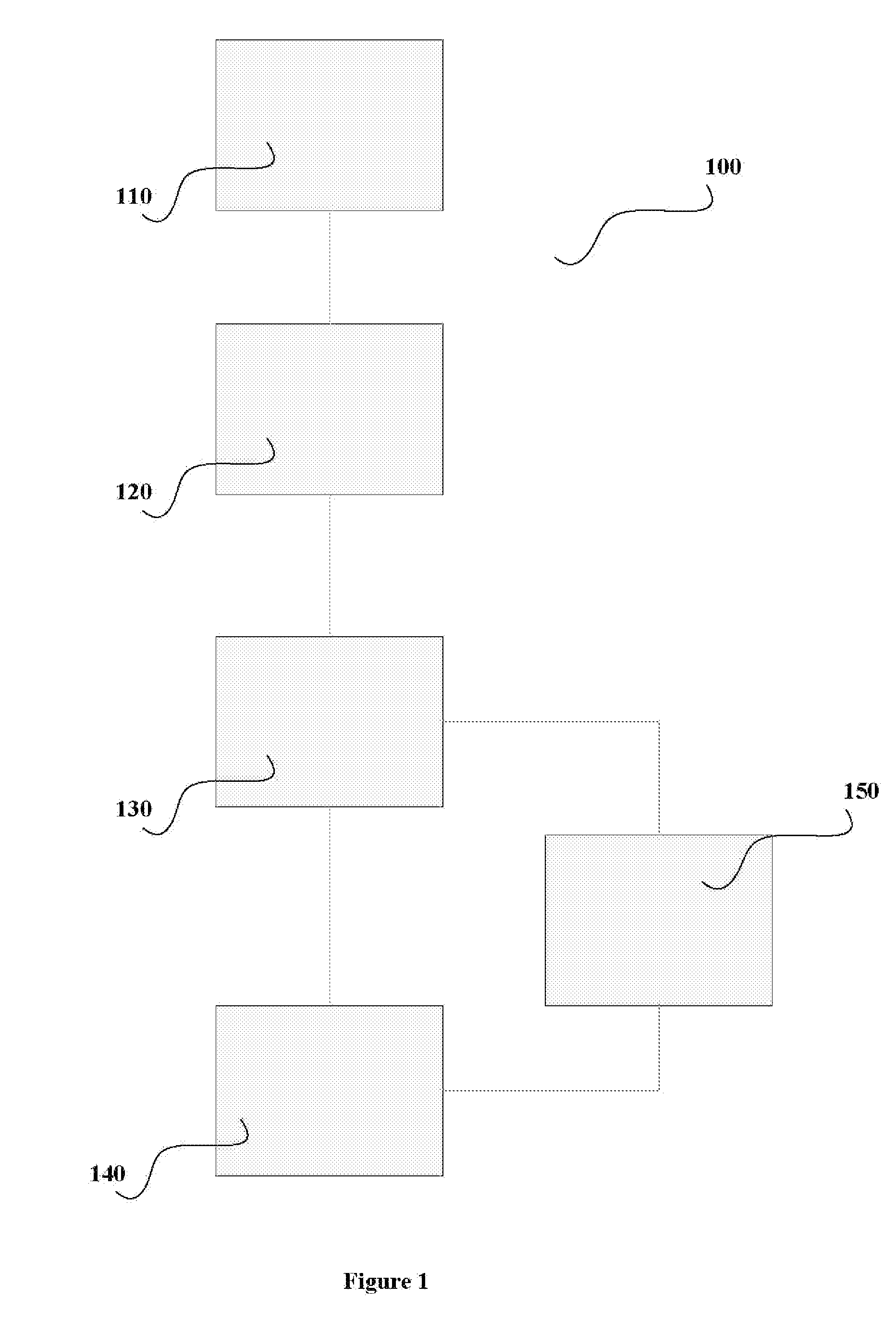
[0052]Referring to FIG. 1, there is seen a flowchart of a high level overview of the method 100 in accordance with the teachings of this invention. The scope of this invention entails the design process of customizing an enclosure for internal components, for example, a printed circuit board (PCB). It is assumed that general knowledge of enclosure design is known, such as metal selection, bend radii requirements, welding and finishing.

[0053]As a first step 110 in the overall method in accordance with the teachings of this invention, the client or user determines the appropriate route to take in designing the enclosure. The user can choose between a design template provided by the software in accordance with the teachings of this invention and a CAD template as detailed below.

[0054]In general, the design process 120 entails selecting a face, cutouts and standoffs. Once the design is complete (the process of which is detailed below), the user can request a price quote in step 130 and / ...


PUM


Abstract

Disclosed are a method, a computer-based system and a computer-readable medium having computer-readable code embodied therein for creating the specifications for the fabrication of a fully customized enclosure housing internal components. First a suitable three dimensional template representing a basic form of the enclosure is chosen from a plurality of predetermined three dimensional templates and sized. Each face of the enclosure is selected and customized by selecting specific design features from a range of predetermined design options as necessary until a complete set of specifications for the enclosure is obtained.

Description

FIELD OF THE INVENTION[0001]The present invention relates to the fabrication of enclosures such as metal enclosures for housing internal components, such as printed circuit boards.BACKGROUND OF THE INVENTION[0002]Enclosures are used in general to house all types of internal components. For example, enclosures are required to house printed circuit boards (PCBs). Most electronic engineers are knowledgeable when it comes to designing PCBs. However, many times, the mechanical challenge is that the enclosure must be custom designed in order to accommodate the PCB, or other electronic components. This process can be difficult and time consuming. Many electronic engineers do not have the tools required to efficiently design enclosures to accommodate their electronic designs.[0003]Software to aid in the design of various mechanical devices is available. One such program is Front Panel Designer (FPD), owned by Front Panel Express LLC. FPD is a template-based computer-aided design (CAD) tool ...

Claims


Application Information

Patent Timeline
Patent Type & Authority Applications(United States)
IPC IPC(8): G06F17/50
CPCG06F17/50G06T2219/2016G06T19/20Y02T10/82G06F30/00
Inventor LILLEY, STEPHEN G.MILBURN, DOUGLAS I.MANLEY, STEPHEN F.
Owner PROTOCASE
Why Eureka
Try Eureka