Magnetic force reciprocating motor

a reciprocating motor and magnetizing force technology, applied in the direction of mechanical energy handling, electrical equipment, dynamo-electric machines, etc., can solve the problem that the amount of pollution produced by automobiles through internal combustion engines cannot be realistically calculated

Inactive Publication Date: 2008-05-29
CRISTOFORO MICHAEL +1
View PDF15 Cites 29 Cited by
  • Summary
  • Abstract
  • Description
  • Claims
  • Application Information

AI Technical Summary

Benefits of technology

[0026]Yet another objective of the invention is to eliminate the need for extensive modifications to the internal combustion engine by allowing most mechanical changes to take place upon replacement of the head gasket with a spacer having an electro-magnet incorporated therein.
[0027]Still another objective of the invention is to address the fuel shortage and provide an alternative to simply having to scrap existing automobiles due to the fuel shortage.

Problems solved by technology

Waste products from the internal combustion engine is heat, which requires elaborate cooling systems to remove, and gas which is vented to the atmosphere and becomes a known pollutant.
The amount of pollution that automobiles produce through their internal combustion engine cannot be realistically calculated.
Thus, what is lacking in the art is a means timed energizing of the magnets for use in a reciprocating motor, thus providing the missing link in converting internal combustion engines to a magnetic force reciprocating motor with sufficient power to properly propel a vehicle.

Method used


Image

  • Magnetic force reciprocating motor
  • Magnetic force reciprocating motor
  • Magnetic force reciprocating motor

Examples


Embodiment Construction

[0035]Although the invention will be described in terms of a specific embodiment, it will be readily apparent to those skilled in this art that various modifications, rearrangements and substitutions can be made without departing from the spirit of the invention. The scope of the invention is defined by the claims appended hereto.

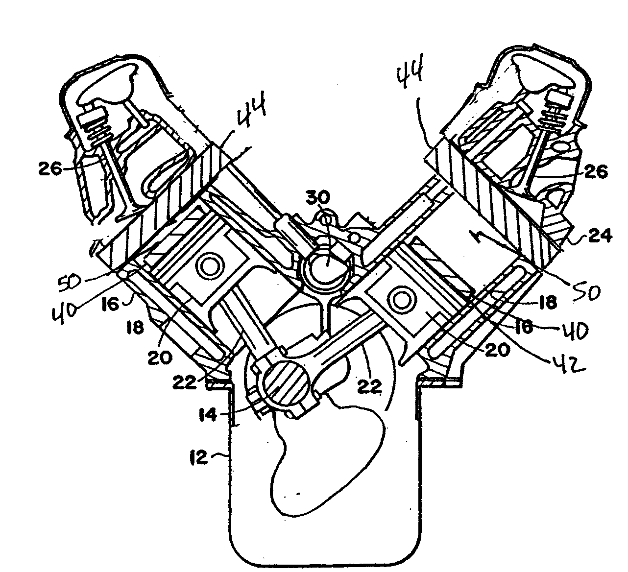
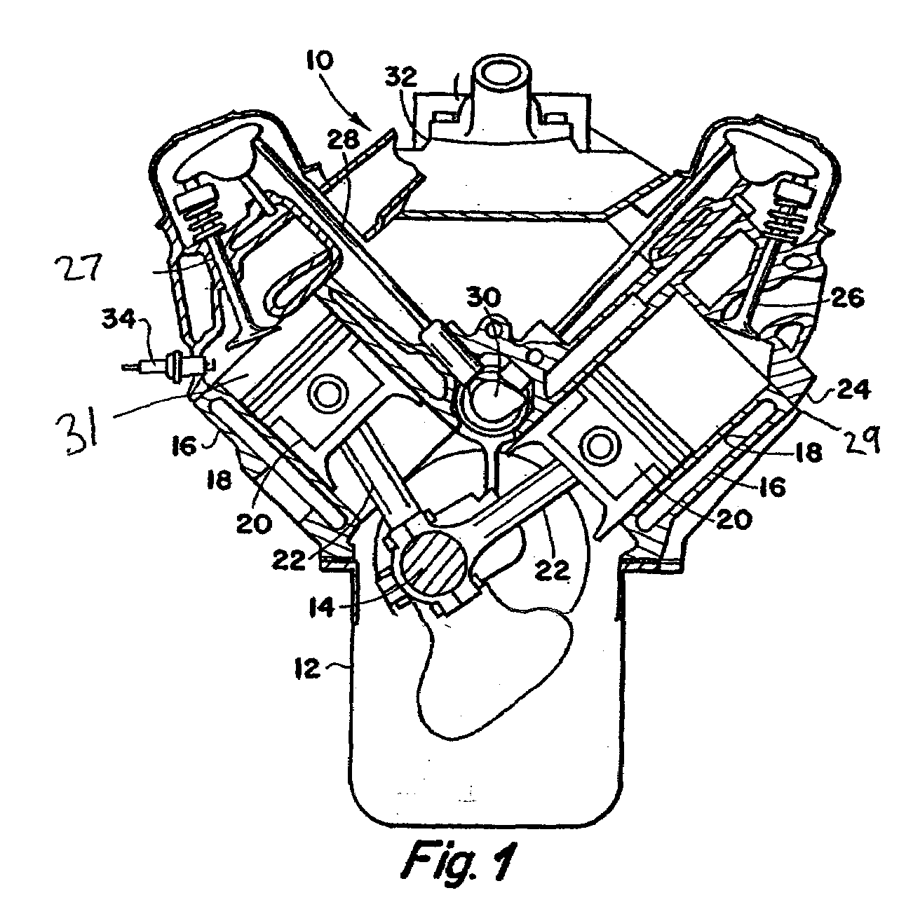
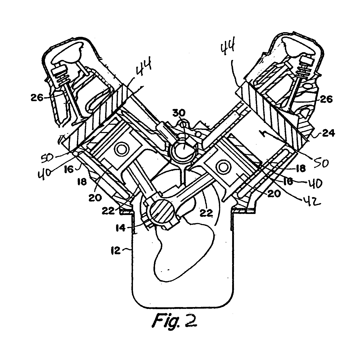
[0036]Now referring to the drawings, a four-cycle internal combustion engine 10 is depicted having an engine block member 12 with a crankshaft 14 being journalled therein. Cylinders 16 are formed integral with the block member 12 with cooling water jackets 18 surrounding the cylinders 16. Reciprocating piston members 20 are slidably disposed within the cylinders 16 and secured to the crankshaft 14 by connecting rods 22. Secured to the engine block member 12, along the outer ends of the cylinder 16 are head members 24 which contain intake valve members 26 and exhaust valve members 27 therein. A head gasket 29 is used to seal the engine block to the head memb...


PUM


Abstract

An electro-magnetic reciprocating engine and method for converting an internal combustion engine to an electro-magnetic reciprocating engine wherein a ferrite magnet is secured to the top of each piston reciprocally disposed in a cylinder, and an electro-magnet spaced apart from said ferrite magnet on the top of each cylinder. The electro-magnets are energized with a constant voltage to create a magnetic field and the ferrite magnets are selectively intermittently polarized when the piston is about one degree past TDC. The ferrite magnets are polarized by contract strike through a distributor allowing the conventional camshaft to provide timing. The distributor is electrically coupled to a DC power source and a capacitor used to provide a stored but adjustable instant burst of voltage to the contact strike to optimize the magnetic field about the ferrite magnet to interact with the magnetic field about the electro-magnet to effect reciprocal motion of the pistons within the cylinders.

Description

FIELD OF THE INVENTION[0001]This invention relates to vehicle drive motors and more particularly, to vehicle drive motors having reciprocating pistons driven by timed electro magnets.BACKGROUND OF THE INVENTION[0002]The internal combustion engine is based upon the use of at least one reciprocating piston that moves up and down inside a cylinder. A one cylinder engine is typically found in lawn mowers. Larger engines, such as those found in an automobile commonly have four, six or even eight cylinders. In a multi-cylinder engine, the cylinders usually are arranged inline, in a V shape, or in a flat / horizontally opposed shape.[0003]In a conventional internal combustion engine, the cylinders and pistons create a chamber where compression and combustion takes place As a piston moves up and down in a cylinder, the difference between the maximum and minimum volume is called the displacement and is measured in liters or cubic centimeters, where 1,000 cubic centimeters equals a liter.[0004]...

Claims


Application Information

Patent Timeline
Patent Type & Authority Applications(United States)
IPC IPC(8): H02K7/06H02K33/00
CPCH02K7/075H02K53/00H02K33/02
Inventor CRISTOFORO, MICHAELMILES, STEPHEN
Owner CRISTOFORO MICHAEL
Why Eureka
Try Eureka