RFID tag antenna and RFID tag

Inactive Publication Date: 2008-05-29
FUJITSU LTD
View PDF12 Cites 9 Cited by
  • Summary
  • Abstract
  • Description
  • Claims
  • Application Information

AI Technical Summary

Benefits of technology

[0032]The present invention is contrived as described above, thereby bringing forth a benefit, as that of the pres

Problems solved by technology

If an article to which an RFID tag is to be attached is made of a metal, and if the antenna is adhesively attached to a surface of the metal, there is a risk of the communication with a reader/writer becoming impossible due to a phenomena of a shift in a resonance frequency and of a red

Method used


Image

  • RFID tag antenna and RFID tag
  • RFID tag antenna and RFID tag
  • RFID tag antenna and RFID tag

Examples


Embodiment Construction

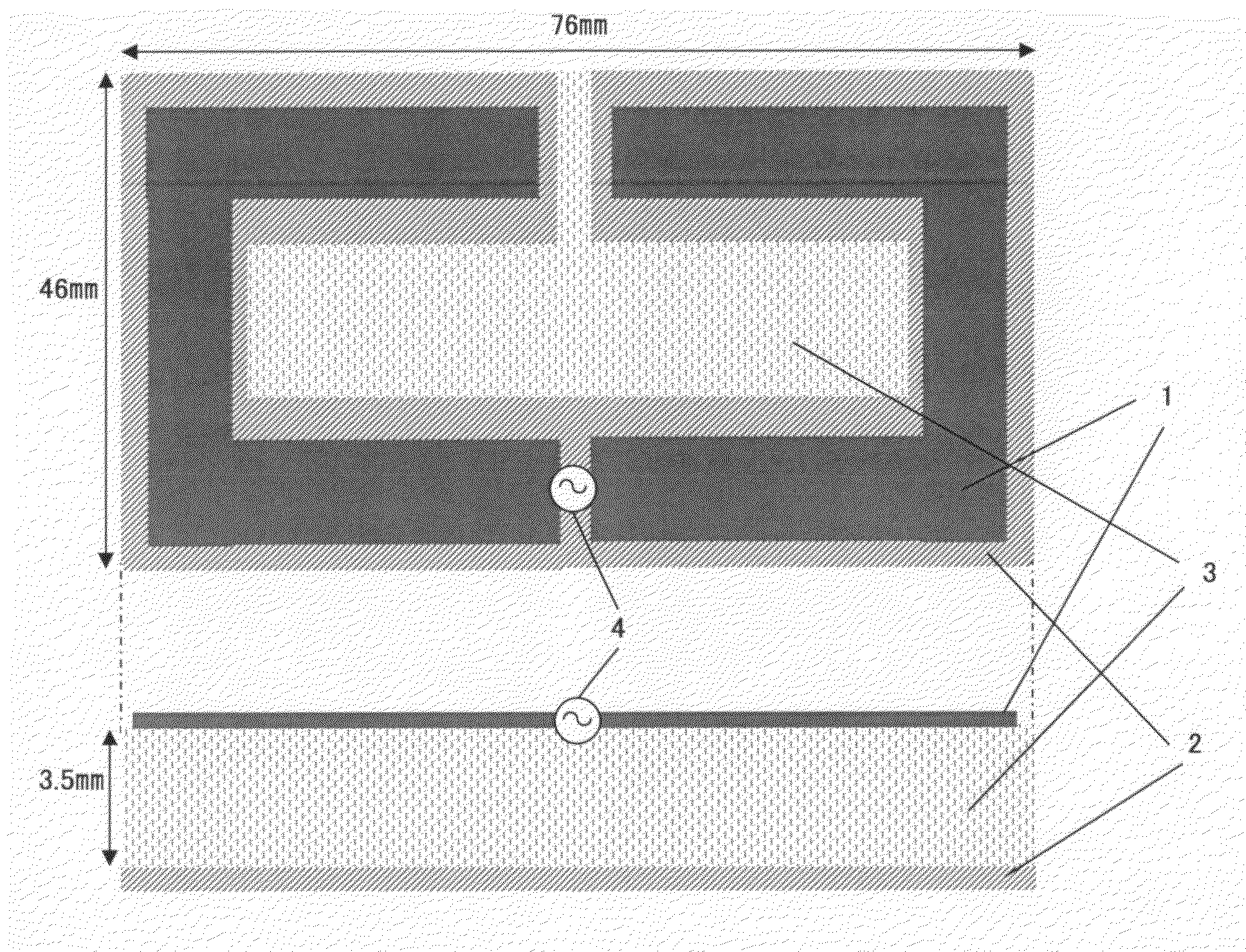
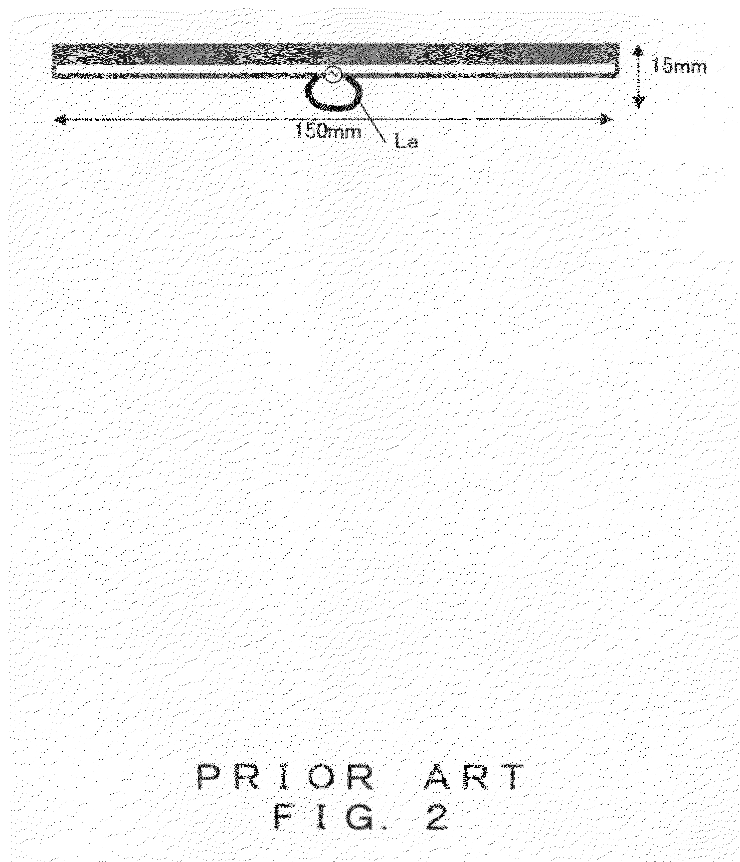
[0044]The following is a description of the preferred embodiment of the present invention by referring to the accompanying drawings. The present embodiment is configured to provide an antenna (i.e., an RFID tag antenna) which has a longitudinal length smaller than that of the above-noted folded dipole antenna, which can make an area size of a face to be adhesively attached to an article no larger than the size of a credit card (i.e., 86 mm long and 54 mm wide, approximately), and which is usable for an RFID tag of a card form.

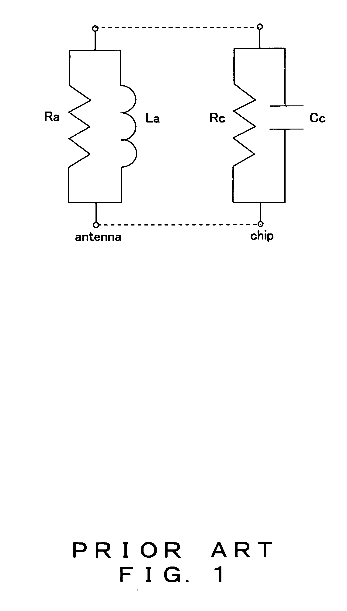
[0045]Note that what is considered in the following description is an RFID tag-use antenna which is connected to an IC chip represented by an equivalent circuit being constituted by a parallel circuit of Cc=0.58 pF and Rc=1200 ohm and which uses a signal of the frequency of 953 MHz. In this case, a setup of the inductance component La of the antenna at around 48 nH constitutes the above described expression 1.

[0046]Note also that the following description shows...


PUM


Abstract

A first pattern is constituted by a pair of conductors each of which comprises only one turn of bent part. An edge part of one side of each of the pair of conductors is configured as a power feeding point. AC coupling section is formed between the power feeding points. And a second pattern is placed opposite to the first element by sandwiching a dielectric body.

Description

CROSS REFERENCE TO RELATED APPLICATION[0001]This application is a continuation application of international PCT application No. PCT / JP2005 / 011074 filed on Jun. 16, 2005.BACKGROUND OF THE INVENTION[0002]1. Field of the Invention[0003]The present invention relates to an antenna technique, and in particular to a technique suitable to an application in an RFID system for reducing a body existing in the surrounding area influencing a performance of the antenna.[0004]2. Description of the Related Art[0005]Known is a system called a Radio Frequency Identification (RFID) system transmitting a signal of approximately one watt from a reader / writer by using a radio signal of the UHF band (860 to 960 MHz) and sending a response signal back to the reader / writer when receiving the signal at a tag side, thereby reading information stored in the tag. A communication distance of the system is about three meters although it depends on an antenna gain on the tag side, an operating voltage of an integr...

Claims


Application Information

Patent Timeline
IPC IPC(8): G08B13/14
CPCG06K19/0723G06K19/07749H01Q9/26H01Q1/2225H01Q1/38G06K19/07771
Inventor KAI, MANABUMANIWA, TORUYAMAGAJO, TAKASHI
Owner FUJITSU LTD
Why Eureka
Try Eureka