
Image processing device, image processing method, and image sensing apparatus

a technology of image processing and image sensing, which is applied in the direction of image enhancement, instruments, television systems, etc., can solve the problems of obstructing the proper reproduction i.e. display of captured images, the effect of wide dynamic range cannot be satisfactorily displayed on the display system having a relatively narrow dynamic range, and the inability to remove the noise component exclusively from the superimposed noise, etc., to achieve the effect of finely removing the noise component, improving noise removal performance, and less or no

Active Publication Date: 2008-05-29
KONICA MINOLTA INC
View PDF12 Cites 79 Cited by
  • Summary
  • Abstract
  • Description
  • Claims
  • Application Information

AI Technical Summary

Benefits of technology

[0016]In view of the above problems residing in the conventional examples, it is an object of the present invention to provide an image processing device that enables to finely remove a noise component with less or no influence of the noise component in an image (i.e. to secure improved noise removal performance), and enables to finely preserve an edge component without likelihood that the noise component may be erroneously detected and preserved as the edge component (i.e. to secure improved edge preservation performance), and consequently enables to obtain a high-quality image, as well as an image processing method, and an image sensing apparatus using the image processing method.

Problems solved by technology

However, in this technique, if superimposed noise that the noise component is superimposed over the real image component is included, it is impossible to exclusively remove the noise component from the superimposed noise.
Even if a wide dynamic range is secured in the imaging system, the effect of the wide dynamic range cannot be satisfactorily exhibited on the display system having a relatively narrow dynamic range, as compared with the imaging system.
Accordingly, a resultantly obtained image has a low contrast, which obstructs proper reproduction i.e. display of the captured image.
Specifically, in the technique disclosed in D1, it is impossible to isolate the noise component from the superimposed noise in a condition that the noise component is superimposed on the real image component, and accordingly, it is impossible to exclusively remove the noise component from the superimposed noise.
However, as far as the ordinary dynamic range image is processed, a serious drawback is not involved, because the noise component with respect to the real image component is negligibly small.
However, in the case where the wide dynamic range image is processed, it is highly likely that the noise component with respect to the real image component may be significantly large.
As a result, the noise component in the image may be intolerably large.
Therefore, it is highly likely that the noise component may remain in the high-frequency component.
If such a phenomenon occurs, the noise component may adversely affect the image because it is highly likely that the noise component is non-negligibly large in the wide dynamic range image.

Method used


Image

  • Image processing device, image processing method, and image sensing apparatus
  • Image processing device, image processing method, and image sensing apparatus
  • Image processing device, image processing method, and image sensing apparatus

Examples


first embodiment

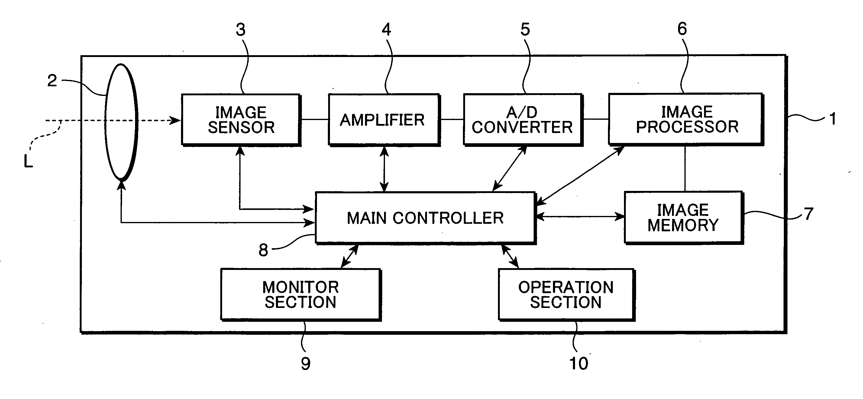
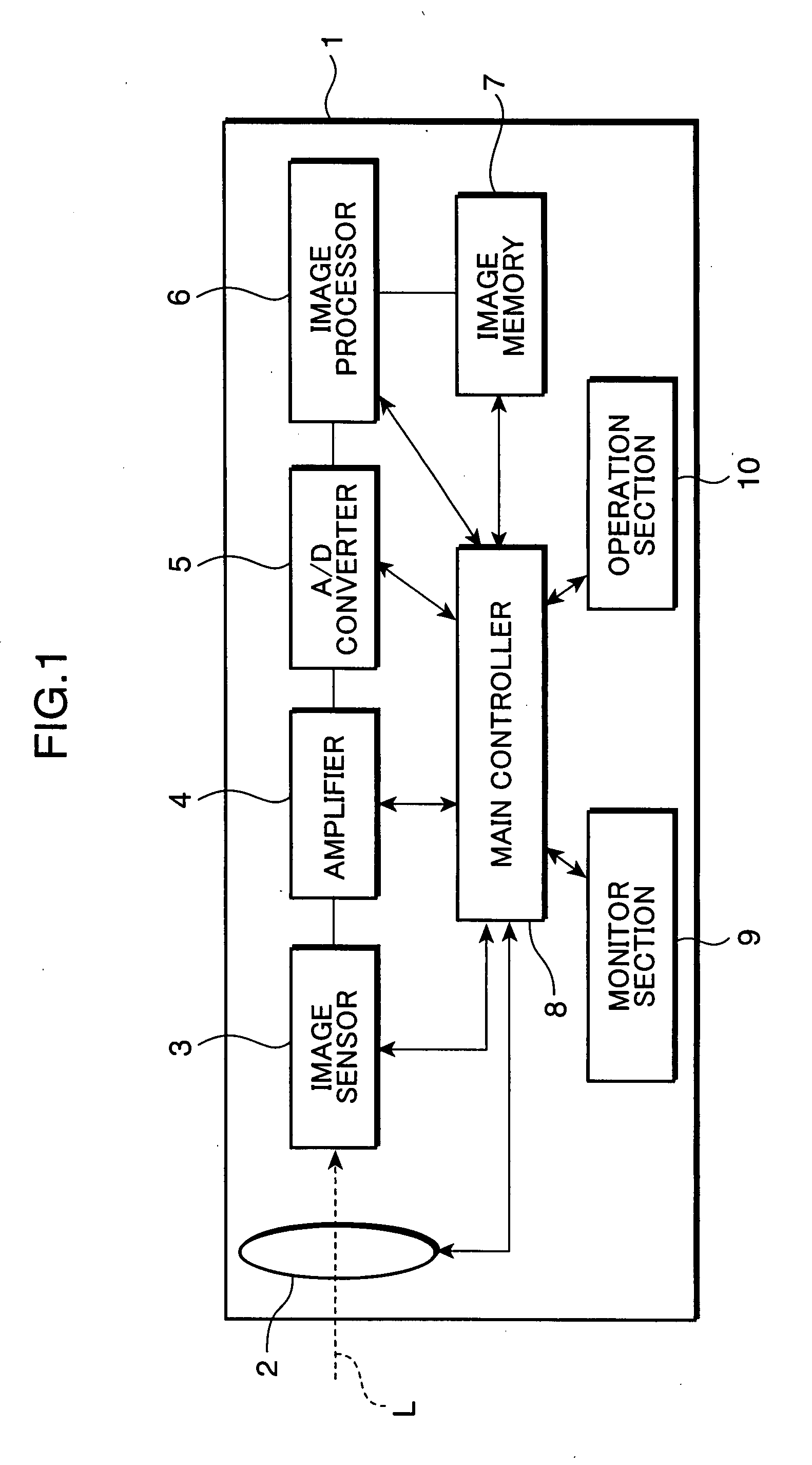
[0043]FIG. 1 is a block diagram primarily showing an imaging process to be executed by a digital camera, as an example of an image sensing apparatus to which an image processing device of a first embodiment of the invention is applied. As shown in FIG. 1, the digital camera 1 includes a lens section 2, an image sensor 3, an amplifier 4, an A / D converter 5, an image processor 6, an image memory 7, a main controller 8, a monitor section 9, and an operation section 10.

[0044]The lens section 2 functions as a lens aperture for taking subject light i.e. a light image, and serves as an optical lens system for guiding the subject light toward the image sensor 3 disposed in the interior of the camera body. The optical lens system is e.g. a lens group arranged in series along an optical axis L of the subject light, and including e.g. a zoom lens, a focus lens, and other fixed lens blocks. The lens section 2 includes a diaphragm (not shown) and a shutter (not shown) for adjusting a light trans...

second embodiment

[0097]FIG. 13 is a functional block diagram showing a circuit arrangement primarily relating to a noise removal processing to be executed by an image processor 6a of a digital camera la in a second embodiment of the invention. The image processor 6a is substantially different from the image processor 6 in the first embodiment in the edge component preservation processing. Specifically, the image processor 6a is provided with a high frequency generator 64′ i.e. an HPF unit 64′, an edge detecting unit 65′, and a noise removing unit 66′, and is further provided with an adding section A and a subtracting section S. The arrangements and the operations of the aforementioned parts are described in detail referring to FIGS. 14 and 15. The elements of the image processor 6a which are substantially equivalent to those of the image processor 6 are denoted with the same reference numerals, and description thereof will be omitted herein.

[0098]FIG. 14 is a partially enlarged view of the HPF unit ...

third embodiment

[0129]FIGS. 19 and 20 are functional block diagrams showing a circuit arrangement primarily relating to a noise removal processing to be executed by an image processor 6b of a digital camera 1b in a third embodiment of the invention. The image processors 6b shown in FIGS. 19 and 20 are the image processor 6b as a subband division functioning part, and the image processor 6b as a subband synthesis functioning part, respectively. In this embodiment, an input image to be inputted to the image processor 6b is divided into plural frequency components i.e. subbands or frequency bands by a Wavelet transformation, the frequency components are subjected to a noise removal processing and an edge component preservation processing, and the processed frequency components are synthesized into an output image. These operations will be described in detail in the following.

[0130]As shown in FIGS. 19 and 20, the image processor 6b includes: a subband dividing unit D0 comprised of a first subband divi...


PUM


Abstract

An image processing device includes: a frequency divider for performing a frequency division processing of dividing an input image into a plurality of frequency components each having a frequency band; a noise remover for performing a noise component removal processing of removing a noise component from a high frequency component in the frequency components each having the frequency band obtained by the frequency division processing by the frequency divider; an edge preservation information calculator for detecting an edge intensity based on a low frequency component in the frequency components each having the frequency band obtained by the frequency division processing by the frequency divider, and calculating edge preservation information relating to a degree of preserving an edge component based on the detected edge intensity; an edge preserving section for preserving the edge component in the high frequency component, based on the edge preservation information calculated by the edge preservation information calculator; and a frequency synthesizer for synthesizing the high frequency component whose noise component is removed by the noise remover and whose edge component is preserved by the edge preserving section, and the low frequency component, in each of the frequency bands.

Description

[0001]This application is based on Japanese Patent Application No. 2006-185415 filed on Jul. 5, 2006, the contents of which are hereby incorporated by reference.BACKGROUND OF THE INVENTION[0002]1. Field of the Invention[0003]The present invention relates to an image processing device capable of removing noise from an image, and more particularly to an image processing device that enables to remove noise from a wide dynamic range image obtained by an image sensing apparatus capable of performing a wide dynamic range imaging, an image processing method, and an image sensing apparatus using the image processing method.[0004]2. Description of the Related Art[0005]An image sensing apparatus such as a digital camera is provided with a predetermined image sensor to capture an image by an imaging operation of the image sensor. Generally, an image i.e. an image signal captured by an image sensor includes a noise component resulting from e.g. a dark current inherent to the image sensor. In re...

Claims


Application Information

Patent Timeline
IPC IPC(8): H04N5/217H04N5/00G06K9/40G06T5/00G06T5/20H04N1/409
CPCG06T5/10G06T7/0085H04N5/217H04N5/35509G06T2207/20208G06T5/50G06T2207/20016G06T2207/20192G06T5/002G06T7/13H04N23/81H04N25/571G06T5/70
Inventor WAKAHARA, JUNYASATO, KAZUCHIKAKAMON, KOICHI
Owner KONICA MINOLTA INC
Learn More