Movable Body System, Exposure Apparatus, And Device Manufacturing Method

a technology of exposure apparatus and body, applied in the direction of photomechanical treatment, printing, instruments, etc., can solve the problems of reducing the depth of focus, becoming much shorter, and reducing so as to achieve the effect of improving the productivity of high-integration microdevices

Inactive Publication Date: 2008-05-29
NIKON CORP
View PDF11 Cites 29 Cited by
  • Summary
  • Abstract
  • Description
  • Claims
  • Application Information

AI Technical Summary

Benefits of technology

[0018]Further, in a lithography process, by transferring a device pattern on a substrate using the first to third exposure apparatus of the present invention, productivity of high integration microdevices can ...

Problems solved by technology

However, although such shorter wavelength of the exposure light and increase in the numerical aperture improve the resolution of the projection exposure apparatus, they also cause the depth of focus to decrease.
Further, it is presumed that the wavelength will become much shorter in the future, and if the situation continues, the risk occurred of the depth of focus becoming so small that focus margin shortage would occur during the exposure operation.
However, in the e...

Method used


Image

  • Movable Body System, Exposure Apparatus, And Device Manufacturing Method
  • Movable Body System, Exposure Apparatus, And Device Manufacturing Method
  • Movable Body System, Exposure Apparatus, And Device Manufacturing Method

Examples


Embodiment Construction

[0033]An embodiment of the present invention will be described below, based on FIGS. 1 to 9.

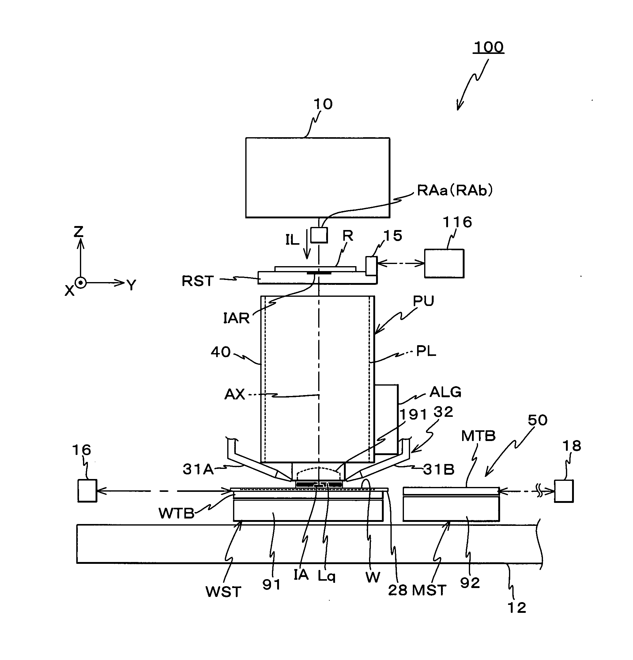
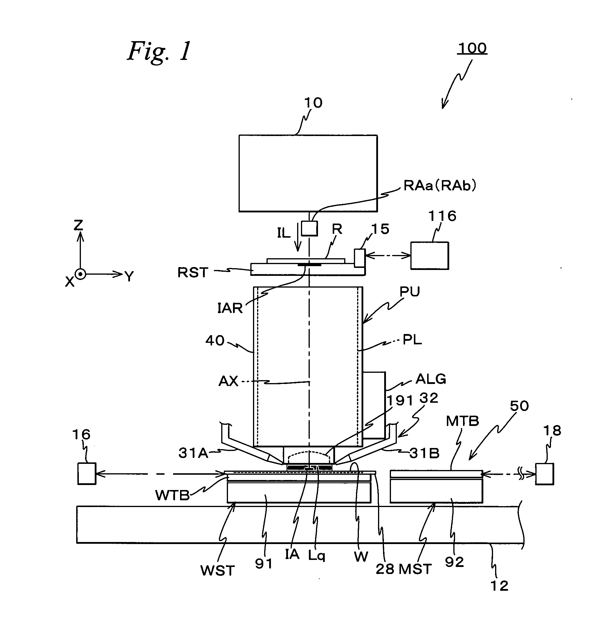
[0034]FIG. 1 shows the entire configuration of an exposure apparatus 100 related to the embodiment. Exposure apparatus 100 is a scanning exposure apparatus by a step-and-scan method, that is, the so-called scanner.

[0035]Exposure apparatus 100 includes an illumination system 10, a reticle stage RST that holds a reticle R which is illuminated by an exposure illumination light (hereinafter also referred to as an “illumination light” or “exposure light”) IL from illumination system 10, a projection unit PU including a projection optical system PL which projects illumination light IL emitted from reticle R on a wafer W, a stage unit 50 that has a wafer stage WST and a measurement stage MST, a control system for these parts and the like. Wafer W is to be mounted on wafer stage WST.

[0036]As is disclosed in, for example, Kokai (Japanese Unexamined Patent Application Publication) No. 2001-313250 and i...


PUM


Abstract

Stopper mechanisms keep a wafer table and a measurement table from moving closer than a predetermined distance, and the blocking by the stopper mechanisms can also be released by a drive mechanism. Therefore, for example, in the case X-axis stators are driven independently, even if at least one of the two tables go out of control, the stopper mechanisms can keep the tables from coming into contact with each other, and for example, in the case the tables are to be in a state closer than the predetermined distance, by a release mechanism that releases the blocking of the stopper mechanisms, the tables can approach each other without the stopper mechanisms interfering.

Description

TECHNICAL FIELD[0001]The present invention relates to movable body systems, exposure apparatus, and device manufacturing methods, and more particularly to a movable body system that has two movable bodies which can be moved independently in a predetermined uniaxial direction, an exposure apparatus that is equipped with the movable body system, and a device manufacturing method in which a device pattern is transferred onto a substrate using the exposure apparatus.BACKGROUND ART[0002]Conventionally, in a lithography process for manufacturing electronic devices such as a semiconductor (an integrated circuit or the like), a liquid crystal display device or the like, a reduction projection exposure apparatus by a step-and-repeat method (the so-called stepper) that transfers a pattern of a mask (or a reticle) via a projection optical system onto each of a plurality of shot areas on a photosensitive object such as a wafer, a glass plate or the like on which a resist (a photosensitive agent...

Claims


Application Information

Patent Timeline
IPC IPC(8): G03B27/42G03B27/58
CPCG03F7/70341G03F7/70725H01L21/682G03F7/709G12B5/00G03F7/70733G03F7/2041G03F7/2049G03F7/70808H01L21/0274
Inventor YODA, YASUSHISHIBAZAKI, YUICHIARAI, DAI
Owner NIKON CORP
Why Eureka
Try Eureka