Timepiece component and timepiece having the timepiece component

a timepiece and component technology, applied in instruments, horology, gearworks, etc., can solve the problems of increasing the coefficient of friction to approximately 0, rough plating at the contact surface, increasing the coefficient of friction, etc., to improve the oil retention of sliding friction parts, improve wear resistance and lubricity, and facilitate long-term use of timepieces.

Inactive Publication Date: 2008-05-29
SEIKO EPSON CORP +1
View PDF6 Cites 7 Cited by
  • Summary
  • Abstract
  • Description
  • Claims
  • Application Information

AI Technical Summary

Benefits of technology

[0018]A timepiece part and a timepiece having the timepiece part according to the present invention (1) enable long-term use of a timepiece without lubrication by significantly improving the wear resistance and lubricity of sliding friction parts and switching parts, and (2) improve the oil retention of sliding friction parts and switching parts and enable long-term use of a timepiece without reapplying an oil dispersion prevention process.
[0019]With respect to (1), the inventors discovered a method of reducing the coefficient of friction and dramatically improving wear resistance and lubricity by coating the sliding friction parts or switching parts of a timepiece component with a composite plating containing carbon nanotubes in a metal plating, and thereby enabling using the timepiece for a long time without regular disassembly, cleaning, and lubrication.

Problems solved by technology

Special horological oils are used to impart wear resistance and lubrication to these sliding friction parts and switching parts because they tend to wear easily due to point contact with other timepiece parts.
The rapid rise in the coefficient of friction to approximately 0.6 between 0 to 200 strokes is thought to be because great force is temporarily applied due to contact with other timepiece parts, and the plating at the contact surface is rough and wears.
It is also thought that the subsequent increase in the coefficient of friction is due to waste produced from wear of the contact surface plating adhering to the contact surface as the number of strokes increases.
Lubrication stabilizes the coefficient of friction within the limits of the test described above, but even when such timepiece parts are lubricated using a horological oil, the oil degrades and the friction resistance increases during use over long periods of time and in low temperature environments.
This leads to the problem of increased energy consumption and the timepiece even stopping.
However, because great force is momentarily applied by point contact with other timepiece parts to these sliding friction parts and switching parts, friction resistance is increased by the contact surface wearing and becoming rough and by the waste produced by contact surface wear adhering to the contact surface.
In other words, realizing lubrication-free timepiece parts is difficult.
Even when such an oil dispersion prevention process is applied, however, oil retention degrades over extended use and the oil scatters and flows.
If the thickness of the nickel plating is less than 2 μm, carbon nanotubes cannot be sufficiently mixed into the nickel plating and the composite plating can therefore not be formed on the timepiece component.
On the other hand, if the thickness of the nickel plating is greater than 20 μm, variation in the film thickness of the nickel plating increases and the dimensional precision required for a timepiece component cannot be maintained.
The wear resistance, lubricity, and oil retention of the contact surface of the sliding friction part or switching part cannot be sufficiently improved if the length of the carbon nanotubes is shorter than 10 μm because a carbon nanotube layer cannot be sufficiently formed.
In addition, the wear resistance, lubricity, and oil retention of the contact surface of the sliding friction part or switching part can be sufficiently improved if the carbon nanotubes are longer than 20 μm, but because the wear resistance, lubricity, and oil retention do not correspond to the length of the carbon nanotubes, this mixes carbon nanotubes uselessly with the nickel plate.
More specifically, if the carbon nanotube content to the metal plating is less than 0.05 wt %, the wear resistance, lubricity, and oil retention can be improved in the contact surface of the sliding friction part or switching part, but the coefficient of friction cannot be lowered to a level where the timepiece can be used for a long time without regular disassembly, cleaning, and lubrication or repeating the oil dispersion prevention process.
Furthermore, if the carbon nanotube content to the metal plating is greater than 1 wt %, the dispersant content also increases, and plating defects including adhesion and cracking problems can occur.
Reduction in the coefficient of friction also reaches the saturation level, and increasing the carbon nanotube content uselessly mixes more carbon nanotubes in the nickel plating.
The pinion and pivot in wheel train components for a timepiece are parts that rotate sliding against other timepiece components to move the hands, rotate sliding in one direction during normal timepiece operation, and are therefore timepiece components that are particularly susceptible to wear.
The setting lever and yoke of the setting mechanism are parts of which the contact with other parts changes when the timepiece user adjusts the hands to set the time, and are timepiece components that are particularly susceptible to wear.

Method used


Image

  • Timepiece component and timepiece having the timepiece component
  • Timepiece component and timepiece having the timepiece component
  • Timepiece component and timepiece having the timepiece component

Examples


embodiment 1

[0056]General Arrangement of an Electronically-Controlled Mechanical Timepiece

[0057]A first embodiment of the invention is described below with reference to the accompanying figures.

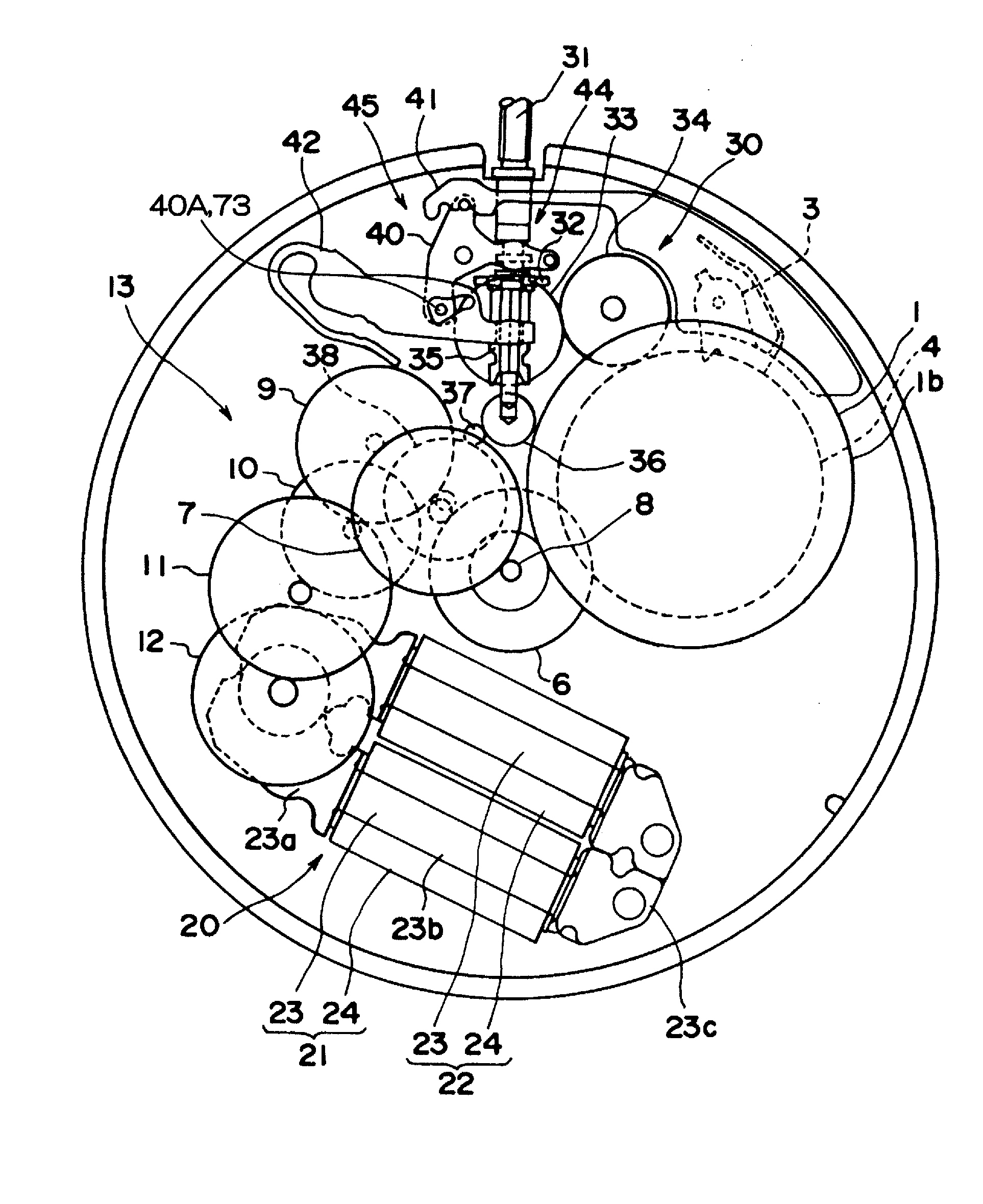
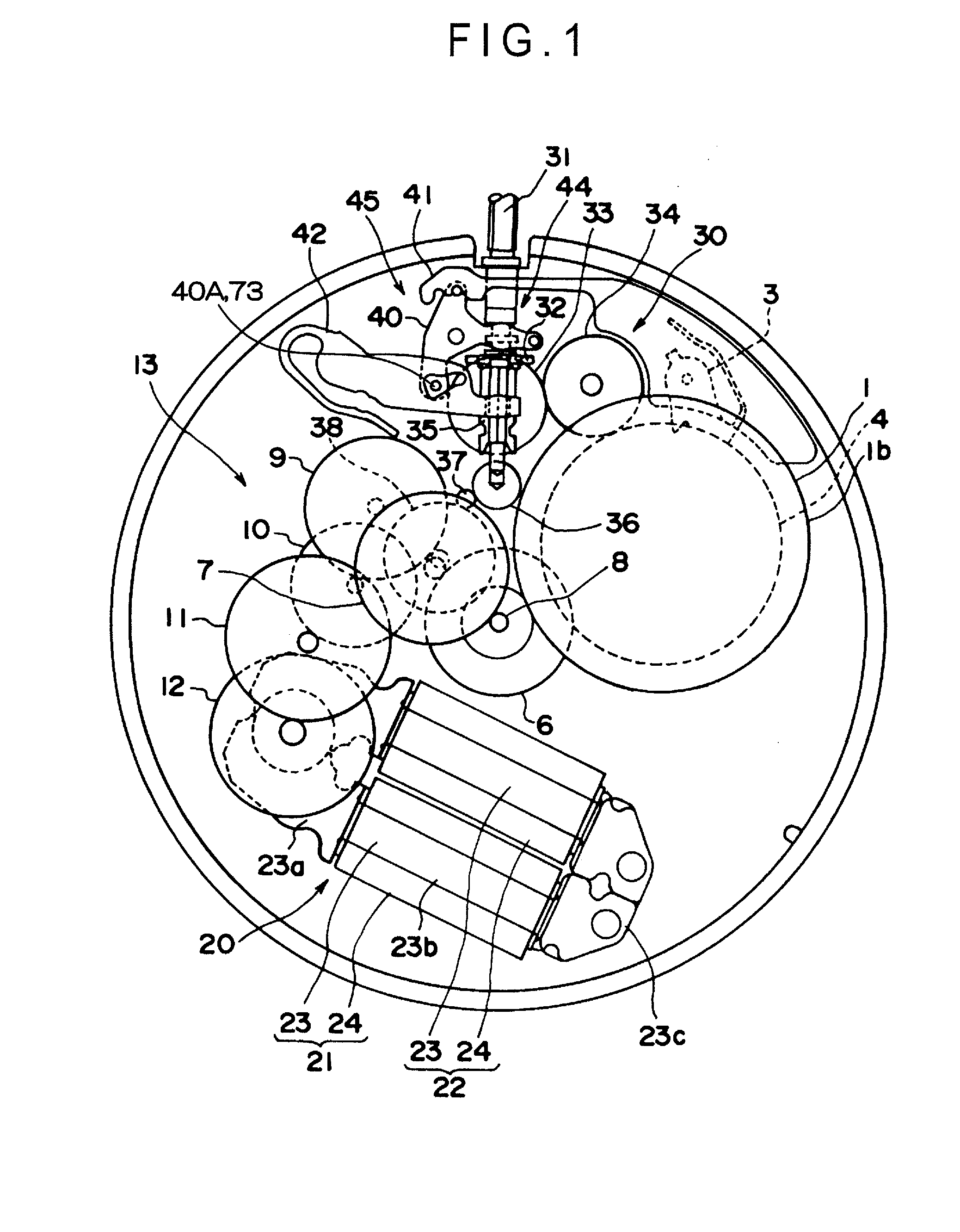
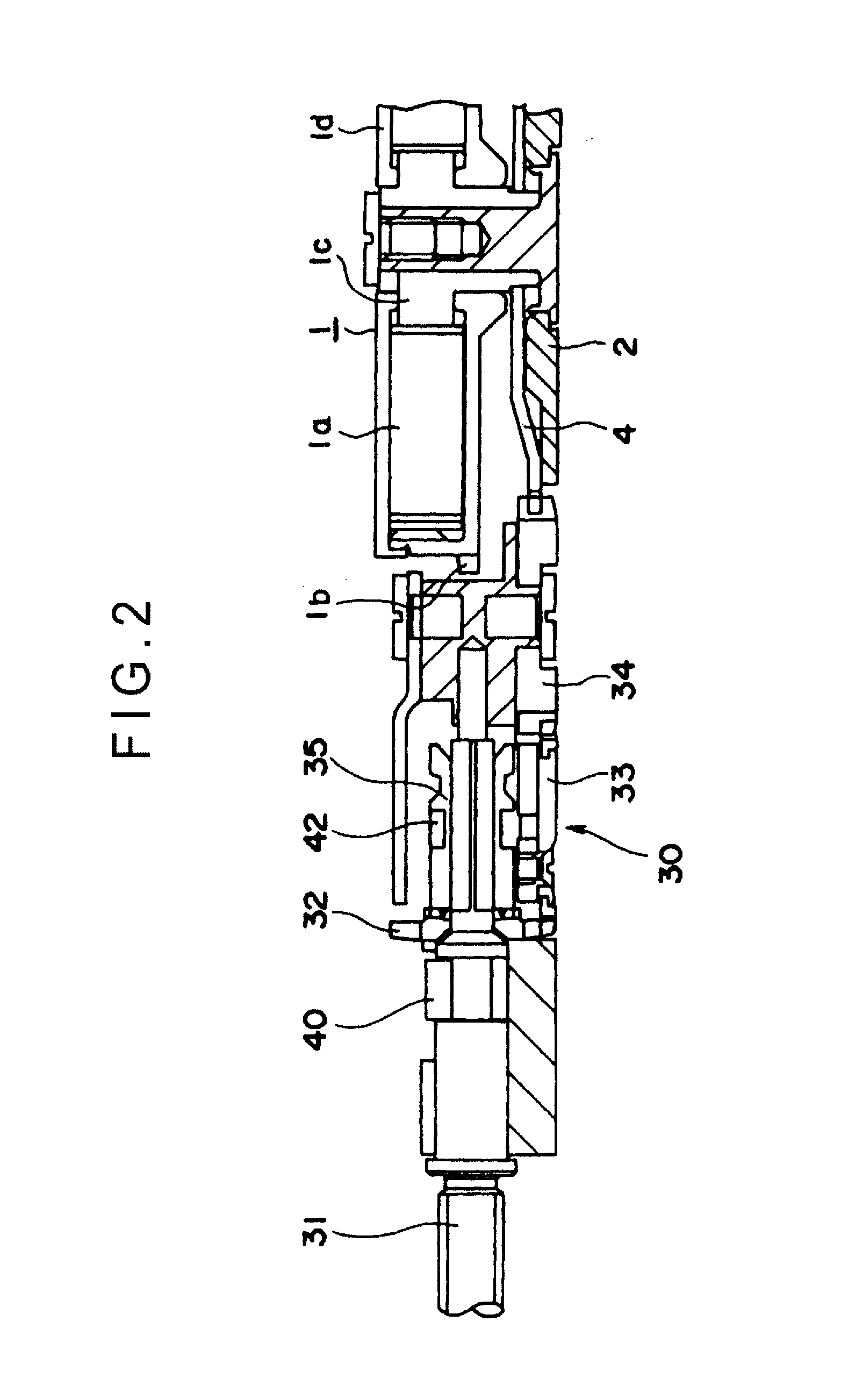
[0058]FIG. 1 is a schematic plan view of an electronically-controlled mechanical timepiece according to this embodiment of the invention, and FIG. 2 and FIG. 3 are section views showing a main part of FIG. 1.

[0059]As shown in FIG. 1 to FIG. 3, the electronically-controlled mechanical timepiece has a mainspring 1a, a barrel wheel 1b, a barrel arbor 1c, and a barrel cover 1d. The outside end of the mainspring 1a is fixed to the barrel wheel 1b and the inside end is fixed to the barrel arbor 1c. The barrel arbor 1c is supported on the main plate 2, and rotates in unison with the ratchet wheel 4.

[0060]The ratchet wheel 4 rotates clockwise and engages a detent 3 so that the ratchet wheel 4 does not rotate counterclockwise. The ratchet wheel 4 is arranged so that when a winding stem 31 connected to a crown not...

embodiment 2

[0098]A second embodiment of the invention is described next. As shown in FIG. 8 this embodiment of the invention lubricates between the third pinion 71 and bottom pivot 72 and the pivot hole 51 with a special horological oil 76. Except for this use of lubrication, the arrangement of a timepiece according to this embodiment of the invention is the same as the timepiece according to the first embodiment.

[0099]FIG. 9 is an enlarged view of the surface of the third pinion 71 and bottom pivot 72 coated with a composite plating 73.

[0100]As shown in FIG. 9 the horological oil 76 is held by the carbon nanotubes 75A in the carbon nanotube layer 75. Because the carbon nanotube layer 75 is unoriented, the oil is impeded from flowing in any direction and the oil is retained uniformly.

[0101]As in the first embodiment, the surfaces of the third pinion 71 and the bottom pivot 72, or more specifically the surfaces that contact the pivot hole 51, are coated with a composite plating 73 (FIG. 4) in t...


PUM

PropertyMeasurementUnit
thicknessaaaaaaaaaa
lengthaaaaaaaaaa
surface roughness Raaaaaaaaaaa

Abstract

A timepiece component having a sliding friction part that slides in contact with another timepiece component, or a switching part that changes the contact state with another timepiece component in response to an operation operating the timepiece, wherein the contact surface of the sliding friction part or switching part is coated with a composite plating containing carbon nanotubes in a metal plating.

Description

BACKGROUND[0001]1. Field of Invention[0002]The present invention relates to a timepiece component and to a timepiece having the timepiece component.[0003]2. Description of Related Art[0004]Composite plating having fine particles mixed in a metal plating that are formed by a eutectic reaction of a metal mixed with insoluble particles in a common electroplating bath or chemical plating bath are known from the literature. Composite plating enables forming a coating with outstanding hardness, wear resistance, lubricity, and other desirable characteristics by appropriately selecting the metal plating and particle materials. See, for example, Japanese Unexamined Patent Appl. Pub. JP-A-2006-28636.[0005]The composite plating taught in JP-A-2006-28636 can form a composite plating featuring high hardness and a smooth surface by mixing carbon nanotubes as the particles in a nickel plating as the metal plating by mixing a brightener, polyacrylic acid, and carbon nanotubes in a Watts bath of pri...

Claims


Application Information

Patent Timeline
Patent Type & Authority Applications(United States)
IPC IPC(8): G04B13/00
CPCC25D15/02G04D3/0094G04B27/04
Inventor FUJIMORI, AKIHIROMURAI, MASAMIARAI, SUSUMU
Owner SEIKO EPSON CORP
Why Eureka
Try Eureka